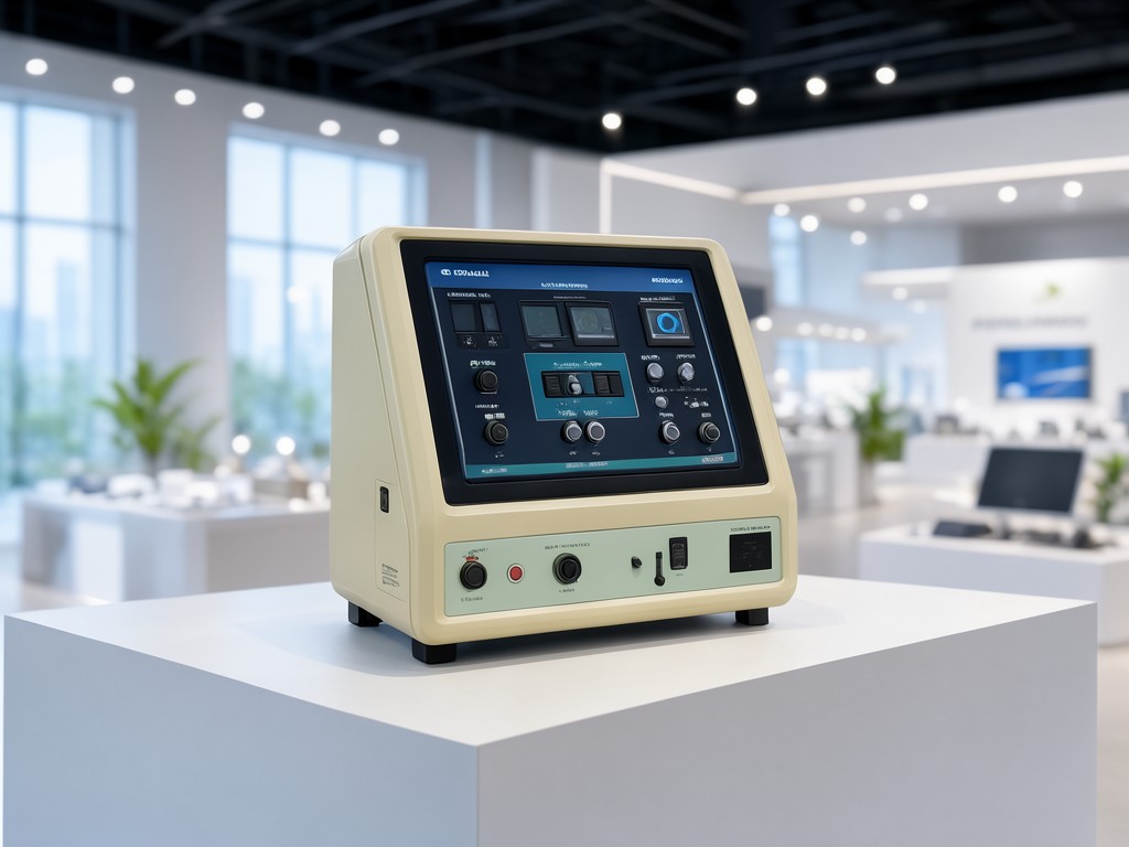
b2b transformer tan delta tester price: Specification, Ordering and Quality Notes
Weight and stiffness trade off against each other in the high-voltage test set: a 12 kV unit with a 200 VA resonant supply fits in a 15 kg pelican case, but the same topology at 10 kV / 500 VA pushes the transformer core past 18 kg and forces a trolley frame. Buyers who specify the lighter unit for substation walk-throughs find the 30-second recharge cycle between measurements adds two hours to a 20-bushing job, while the heavier cart-mounted version sustains continuous testing but won't fit through a standard 600 mm cabinet door. The decision rule is simple: if the crew moves between bays more than three times per shift, accept the recharge penalty; if they park beside a transformer for the day, specify the continuous-duty core and budget the freight surcharge.
The limiting factor is rarely the headline specification — 0.001 % tan delta resolution looks identical on every datasheet — but the stability of that resolution after 50 thermal cycles from -10 °C to 45 °C. We see returns where the reference capacitor drifts 15 ppm/°C because the factory sourced a cheaper NP0 dielectric batch, and the firmware compensation table was never updated for the new lot. That drift turns a 0.5 % tan delta reading into 0.53 % on a 220 kV bushing, enough to trigger a false "marginal" classification and an unplanned outage. Lot-to-lot consistency on the reference standard and the HV divider ratio is what the buyer actually pays for, not the digit count on the display.
Design Constraints Behind the Specification
Critical Specification Rule
The test voltage must exceed the equipment rated voltage by at least 1.5× for tan delta trending to be meaningful. A 10 kV test set on 11 kV class cables only reaches 0.9× Ur — insufficient to stress voids in XLPE insulation. Specify 12 kV minimum for 11 kV networks, 24 kV for 22 kV networks. The 0.5 kV step resolution below 2 kV is a marketing figure; the HV relay contact bounce makes steps below 1 kV unreliable in field conditions.
The resonant test topology — variable inductor plus fixed capacitor — keeps the inverter size down but forces a tuning sequence at every frequency step. Firmware that locks onto resonance in under 3 seconds requires a phase-locked loop with 0.01 ° resolution on the current-voltage phase angle. Cheaper units use a 0.1 ° PLL and hunt for 8-12 seconds per step; on a 20-point frequency sweep that adds four minutes of dead time per bushing. The inductor Q factor drops 15 % after 2,000 hours of 500 VA operation as the ferrite core ages, shifting the resonance point and requiring recalibration. We specify a 10 % Q margin at factory acceptance so the unit stays in spec for the first 18 months without adjustment.
Materials and Construction Trade-offs
Aluminium Enclosure (Standard)
6063-T5 extrusion, 3 mm wall, IP54 with glanded cable entry. Weight: 4.2 kg for 12 kV chassis. Anodised 25 µm, salt-spray 480 h per ISO 9227. RFI shielding 60 dB at 1 MHz — adequate for substation EMI.
Dents on corner drops; the HV connector flange can deform 0.3 mm, changing creepage by 15 %. Repair requires factory realignment.
Stainless Steel Enclosure (Option S)
1.5 mm 316L sheet, welded seams, IP66. Weight: 6.8 kg for same chassis. No anodise to scratch; passivated finish survives coastal depots. RFI shielding 75 dB at 1 MHz — required for GIS hall testing.
Adds 2.6 kg and 18 % unit cost. No field repair on flange; swap the whole front panel assembly (stocked as spare).
The HV output cable is the highest-wear item. Standard 3 m silicone-insulated lead with 25 mm2 copper, rated 30 kV DC, survives 500 mate cycles on the proprietary bayonet connector before the contact fingers lose spring force. The 10 m extended lead (Option L) adds 1.8 kg and 3 pF/m stray capacitance — negligible for tan delta but shifts the resonance frequency 0.8 % at 1 kHz, requiring a firmware offset table. We ship the offset table pre-loaded for the 10 m lead; if the buyer cuts the cable to 7 m, the table is invalid and readings drift 0.003 % absolute. Never cut the HV lead. Order the correct length.
Specification Range and Customisation Limits
| Parameter | Standard Range | Customisation Limit | Lead-time Adder |
|---|---|---|---|
| Test Voltage (AC RMS) | 1 - 12 kV / 1 - 24 kV | Up to 30 kV (requires 35 kV bushing) | +3 weeks |
| Tan Delta Range | 0 - 50 % | 0 - 100 % (software unlock) | None |
| Capacitance Range | 5 pF - 1 µF | 1 pF - 5 µF (external std. cap.) | +1 week |
| Frequency Sweep | 15 - 400 Hz, 20 steps | 10 - 500 Hz, 50 steps (FW v3.2+) | None |
| Display | 7" 800×480 resistive touch | 10.1" 1280×800 capacitive (Option D) | +2 weeks |
| Interface | USB-A, Ethernet, Wi-Fi | Optical Ethernet, 4G modem (Option M) | +2 weeks |
| Power Supply | 90-264 VAC, 47-63 Hz | 18-36 VDC vehicle mount (Option V) | +3 weeks |
Customisation beyond the table requires a new safety file — IEC 61010-2-030 clause 6.2 re-evaluation for any voltage above 30 kV, and clause 10.5.2 for any enclosure material change. That means a 6-week notification to the notified body before first article inspection. Plan the PO date accordingly.
Quality Control and Batch Consistency
Repeat loading drives the failure mode we track most closely: the HV relay (Reed, 30 kV hold-off) rated for 106 operations at 100 mA inductive load. In practice, the inrush from the resonant capacitor peaks at 2.3 A for 40 µs, and the contact erosion follows a power law — 0.8 µm per 104 cycles after the first 50k. We life-test every 50th unit to 200k cycles at full voltage; the batch passes if the contact resistance stays below 120 mΩ and the timing jitter stays below 15 µs. Units from batches that pass ship with a 24-month calibration interval; batches that marginal (120-150 mΩ) ship with a 12-month interval and a red tag on the calibration certificate.
Calibration Traceability Note
Every unit leaves with an ISO 17025-accredited certificate referencing our 100 pF / 10 kV working standard (calibrated annually against the national lab 10 pF fused-silica reference). The certificate states the as-found / as-left tan delta at 0.5 %, 5 %, 20 % using a three-terminal reference capacitor. If your quality system requires a specific lab name on the certificate, tell us at order — we cannot re-issue after shipment.
Inspection Items and Test Methods
| Inspection Point | Method | Acceptance Criterion | Frequency |
|---|---|---|---|
| HV Divider Ratio | Step-voltage comparison vs. 10 kV reference divider | Ratio error ≤ 0.05 % at 1, 5, 10, 12 kV | 100 % production |
| Tan Delta Accuracy | Three-terminal reference capacitor (0.5 %, 5 %, 20 %) | ±0.0005 absolute at 0.5 %, ±0.005 at 20 % | 100 % production |
| Resonance Tuning Time | Automated sweep at 50, 100, 200, 400 Hz | ≤ 3 s per step, zero hunting cycles | 100 % production |
| Partial Discharge (PD) | IEC 60270, 1.5× rated voltage, < 10 pC background | PD ≤ 5 pC at 1.2× Ur | Type test + 10 % batch |
| Thermal Cycling | -10 °C to +45 °C, 5 cycles, 2 h dwell | Tan delta drift ≤ 0.001 % absolute post-cycling | Type test + 5 % batch |
| Vibration (Transport) | IEC 60068-2-64, 1.9 g RMS, 10-200 Hz, 30 min/axis | No loose hardware, calibration unchanged | Type test only |
| EMI Immunity | IEC 61000-4-3, 10 V/m, 80 MHz-2.7 GHz | Reading deviation ≤ 0.002 % during test | Type test + 5 % batch |
Volume Planning and Lead Time
Standard 12 kV aluminium-enclosure units (Configuration A) hold 4 weeks in finished-goods buffer — typically 12-15 units. Configuration B (24 kV) and Option S (stainless) are build-to-order at 6 weeks. Option V (DC vehicle mount) adds a dedicated inverter sub-assembly with its own 3-week procurement lead; the critical path is the 36 V / 600 W isolated DC-DC module, sole-sourced from a German supplier with 14-week factory lead. If you need Option V, place a blanket PO with a 16-week horizon and we will stage the inverter modules against your release schedule.
Calibration consumables — the 100 pF reference capacitor and the 10 kV divider — are stocked at 2× annual demand. A rush recalibration (3-day turnaround) is available if the unit returns to our facility; we do not support field recalibration because the reference standard requires temperature-controlled oil bath (±0.1 °C) during the 4-hour soak. Budget 5 working days plus round-trip freight for any recal event.
Packing, Marking and Freight Configuration
| Item | Specification | Notes |
|---|---|---|
| Outer Case | Peli 1650 (Config A) / Custom plywood crate (Config B, S) | IP67, pressure relief valve, padlock hasps |
| Internal Foam | Custom-cut 2.0 lb/ft³ PE, anti-static pink | Cavities for unit, HV lead, ground lead, accessories |
| Gross Weight | 22 kg (A) / 38 kg (B) / 31 kg (S) | Single-person lift limit 25 kg — Config B requires two-person or trolley |
| Dimensions (L×W×H) | 580×430×280 mm (A) / 720×540×380 mm (B, S) | Fits standard Euro pallet 2-up (A) or 1-up (B, S) |
| Marking | Serial, model, voltage, calibration due date, QR to cert PDF | Laser-etched on rear panel + waterproof label on case lid |
| Freight Class | UN 3480 (Li-ion battery in display) — Class 9 | Requires DG declaration for air freight; sea/road unrestricted |
Care, Storage and Service Life
Store the unit in its case at 15-25 °C, 20-60 % RH. The internal 18650 Li-ion pack (7.2 V, 6.6 Ah) self-discharges 3 % per month; if stored > 6 months without charge, the BMS enters deep-sleep and requires factory reset — not field recoverable. Charge to 60 % SOC before long-term storage. The HV lead silicone insulation stiffens below -5 °C; warm the coil in the vehicle cab for 20 minutes before uncoiling in winter conditions, or the bend radius limit (8× OD) will be exceeded and micro-cracks form at the connector overmould.
Clean the touchscreen with 70 % isopropyl on a lint-free cloth — never spray directly. The resistive panel (standard) tolerates glove pressure; the capacitive Option D does not. HV connector contacts: wipe with dry lint-free swab every 50 insertions. Do not use contact grease — it migrates into the relay and increases erosion rate 3×. The calibration interval is 24 months for standard batches, 12 months for marginal batches (see QC section). Firmware updates via USB-A are signed; unsigned images are rejected by the bootloader. Current production ships v3.1; v3.2 adds the 50-step sweep and Modbus TCP — request at order if required.
Specification Review & Quotation
Send your voltage class, enclosure preference, lead length, and required delivery date. We return a marked-up specification sheet, calibrated price, and confirmed ship week within one business day.
Request Specification Review


