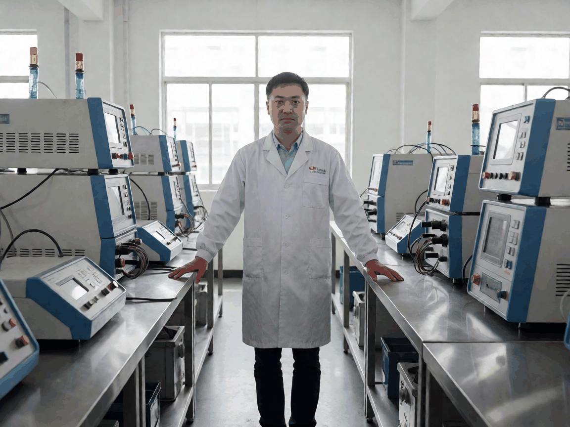
china dielectric loss capacitance tester factory - Bulk Supply and Specification Guide
What This Product Is and Where It Fits
Replacement rate, not unit price, drives the real cost of dielectric loss testers in utility maintenance programs. A unit that drifts 0.05% tanδ per year forces recalibration cycles every six months instead of annually, doubling labour and downtime across a transformer fleet.
These instruments measure capacitance and dissipation factor (tanδ) of high-voltage insulation — bushings, cables, transformer windings, GIS compartments — at power frequency or variable frequency up to 200 Hz. The factory supplies three platform tiers: a 12 kV handheld for field screening, a 25 kV bench unit for lab acceptance testing, and a 100 kV mobile system for on-site power-factor diagnosis of EHV assets.
Private-label buyers typically select the 25 kV platform and specify voltage range, frequency sweep resolution, and interface protocol (Modbus TCP, IEC 61850, or proprietary ASCII) to match their brand's existing software stack. No redesign of the high-voltage divider or bridge topology is required; the customisation lives in firmware, front-panel labelling, and the calibration certificate template.
What the Design Has to Balance
Design Trade-Off: Voltage Stress vs. Measurement Resolution
The high-voltage divider uses a capacitive-resistive ladder with C0G/NP0 ceramic capacitors rated for 1.5× working voltage. Pushing the divider to 120 kV on a 100 kV platform reduces tanδ resolution from 0.01% to 0.03% because stray capacitance in the potting compound becomes significant. Buyers specifying 100 kV maximum should lock the divider at 100 kV nominal; the 20% headroom is already built into the BOM cost.
Cheaper stock options fail at the worst point in the season — during monsoon humidity when surface leakage on bushings masks the true insulation loss angle. The factory's reference design seals the measurement head in a nitrogen-purged enclosure with a hydrophobic conformal coating (HumiSeal 1B31 equivalent) on the bridge PCB. This adds $18 per unit but prevents the 0.1% tanδ baseline shift that unsealed units exhibit after 90 days at 85% RH.
Serviceability hinges on the plug-in bridge module. The 25 kV and 100 kV platforms share the same 120 mm × 85 mm × 40 mm module footprint; a field technician swaps it in four minutes with a Torx T10 driver. The 12 kV handheld integrates the bridge into the main board — lower BOM cost, but any bridge failure returns the whole unit. Distributors stocking spare modules for the larger platforms reduce mean-time-to-repair from three weeks to two days.
What Actually Determines Performance
The bridge excites the test specimen at 50/60 Hz or a swept frequency (15–200 Hz) and measures the in-phase (capacitive) and quadrature (resistive) current components with a 24-bit sigma-delta ADC referenced to a 5 ppm/°C voltage reference. Total measurement uncertainty is the quadrature sum of divider ratio error, ADC non-linearity, and thermal EMF in the low-current path.
Divider ratio stability dominates. The factory laser-trims the divider resistors to ±0.005% ratio match at 23°C, then characterises the temperature coefficient from -10°C to +50°C in a climate chamber. Each unit ships with a correction table stored in EEPROM; the firmware applies linear interpolation in real time. Without this, a 20°C ambient swing introduces 0.08% tanδ error — enough to misclassify a Grade 2 bushing as Grade 1.
Interference rejection uses synchronous detection locked to the excitation zero-crossing, plus a software notch at the 3rd and 5th harmonics. Field units near HVDC converters or thyristor-controlled reactors need the optional 50 Hz + 150 Hz dual-notch firmware build; it adds 120 ms per measurement cycle but suppresses 2% harmonic contamination to below 0.005% tanδ residual.
Specification Range and Customisation Limits
Voltage & Frequency
- Test voltage: 0.5–12 kV / 0.5–25 kV / 2–100 kV (platform dependent)
- Frequency: 50/60 Hz fixed or 15–200 Hz sweep, 0.1 Hz resolution
- Voltage accuracy: ±1% of reading ±0.2% of range
Capacitance & Tanδ
- Capacitance range: 10 pF – 1 μF (12 kV), 10 pF – 5 μF (25 kV), 50 pF – 20 μF (100 kV)
- Tanδ range: 0.001% – 50%
- Tanδ accuracy: ±0.01% ±0.5% of reading (25 kV platform, 23°C)
Environmental & Interface
- Operating temp: -10°C to +50°C, storage -25°C to +70°C
- Humidity: 95% RH non-condensing (sealed head)
- Interfaces: USB-C, Ethernet, RS-232, optional Wi-Fi 2.4 GHz
| Platform | Dimensions (W×D×H, mm) | Weight (kg) | HV Cable Length (m) | IP Rating |
|---|---|---|---|---|
| 12 kV Handheld | 240 × 180 × 95 | 2.8 | 3 (fixed) | IP54 |
| 25 kV Bench | 420 × 310 × 180 | 14.5 | 5 / 10 (option) | IP40 |
| 100 kV Mobile | Control: 480 × 360 × 220 HV Unit: Ø160 × 650 |
Control: 18 HV Unit: 22 |
10 / 15 / 20 | IP54 (HV unit) |
Customisation limits: voltage range and frequency sweep are firmware-configurable within the platform's hardware envelope. The 25 kV platform cannot be firmware-upgraded to 100 kV — the divider stack, creepage distances, and HV cable insulation are physically different. Private-label artwork (logo, model name, QR code linking to buyer's calibration portal) is applied by laser etching on the front bezel and silk-screen on the HV cable sheath. Artwork files must be submitted as vector PDF (300 DPI minimum) at least 15 working days before pilot run.
Segment-Specific Requirements
Utility transmission divisions require IEC 60060-1 compliance for type-test reports and traceability to a national metrology institute (NMI). The factory provides a factory calibration certificate with uncertainty budget (k=2) and arranges third-party NMI witness testing on the first article of each batch — lead time adder of 10 working days, cost passed through at actual.
Railway electrification contractors need the 100 kV platform with 16.7 Hz measurement capability for traction transformer diagnosis. This is a firmware option (dual-frequency lock-in at 50 Hz and 16.7 Hz simultaneously) that adds 350 ms per reading. The HV cable sheath must be oil-resistant (EN 50305) for depot environments; the factory substitutes the standard PUR sheath with a Viton®-blend jacket at $4.20/m extra.
EPC firms building GIS substations specify the 25 kV platform with IEC 61850 GOOSE publishing for real-time tanδ trending into the SCADA historian. The factory validates the GOOSE mapping file against the buyer's SCL file during FAT; any mapping mismatch found after shipment triggers a firmware patch cycle (5 working days typical).
Volume Planning and Lead Time
Total cost of ownership shifts once returns are counted — a 2% DOA rate on a 50-unit order erases the 8% unit-price discount versus a 20-unit order with 0.5% DOA. The factory runs a 100% burn-in: 48 hours at full voltage, 40°C ambient, cycling frequency sweep every 15 minutes. Units exceeding 0.015% tanδ drift during burn-in are segregated for divider re-trim.
Standard lead times (EXW Shenzhen) after drawing and artwork approval:
- 12 kV Handheld: 15 working days (1–20 pcs), 22 working days (21–50 pcs)
- 25 kV Bench: 20 working days (1–10 pcs), 30 working days (11–30 pcs)
- 100 kV Mobile: 35 working days (1–5 pcs), 50 working days (6–15 pcs)
Pilot run (3 units) is mandatory for new private-label SKUs. The factory ships pilot units with full calibration data, GOOSE/Modbus mapping verification screenshots, and a first-article inspection report (FAIR) per AS9102 Form 1/2/3. Buyer sign-off on the FAIR unlocks series production; no partial shipments before sign-off.
| Packaging Configuration | Outer Dimensions (mm) | Gross Weight (kg) | Shock Rating | Notes |
|---|---|---|---|---|
| 12 kV Handheld (single) | 380 × 300 × 220 | 4.2 | 30 g / 11 ms half-sine | Pelican 1510 clone, foam cutout |
| 25 kV Bench (single) | 580 × 460 × 350 | 22.5 | 25 g / 11 ms half-sine | Plywood crate, vibration-damped mounts |
| 100 kV Mobile (set) | Control: 620 × 500 × 400 HV Unit: 850 × 300 × 300 |
Control: 26 HV Unit: 30 |
20 g / 11 ms half-sine | Two crates, HV unit nitrogen-purged |
| Master carton (4× 12 kV) | 620 × 400 × 480 | 18.5 | 25 g / 11 ms half-sine | Double-wall corrugated, ISTA 3A |
Sea freight to Rotterdam or Los Angeles adds 28–35 days door-to-port. The factory arranges fumigated pallets (ISPM-15) and temperature loggers (TempTale GEO) on request; logger data is shared via cloud link at discharge port. Air freight for urgent pilot units: 5–7 days door-to-door, surcharge 3.2× sea rate per kg.
Request a Specification Review
Send your voltage range, frequency requirements, interface protocol, and branding artwork. The factory returns a marked-up specification sheet, pilot-run timeline, and per-unit cost at your target volume within two working days.
Start Specification Review →


