custom advanced capacitance bridge tester suppliers: Specification, Ordering and Quality Notes
Scope of Supply and Physical Form
| Parameter | Standard Configuration | Custom Range | Typical Tolerance |
|---|---|---|---|
| Measurement Range | 1 pF – 100 µF | 0.1 pF – 1 mF (configurable) | ±0.05% of reading |
| Test Frequency | 1 kHz, 10 kHz, 100 kHz | 20 Hz – 2 MHz (programmable steps) | ±0.01% frequency accuracy |
| DC Bias Voltage | 0 – 30 V internal | 0 – 200 V (external bias input) | ±1% of set voltage |
| Interface Options | USB, GPIB | USB, LAN, GPIB, RS-232, Handler I/O | N/A |
| Enclosure | Benchtop, 2U rackmount | Benchtop, 1U/2U/3U rackmount, portable ruggedized | ±0.5 mm dimensional |
The table above defines the baseline envelope. Custom units typically add a programmable frequency synthesizer, extended bias range, and a choice of handler interfaces for automated sorting. Enclosure depth varies with the selected interface complement; allow an extra 40 mm for rear-panel connector clusters when integrating into existing rack layouts.
Weight runs 3.2–4.8 kg depending on shielding and power-supply option. Buyers specifying portable ruggedized versions should budget for a 15% mass increase over the benchtop baseline due to the reinforced chassis and sealed connectors.
The Problem Buyers Keep Paying For
Returns usually trace back to the same weak point: calibration drift that exceeds the published temperature coefficient after six months of daily use. A standard off-the-shelf bridge specifies ±20 ppm/°C; in practice, the reference oscillator and bridge resistors age at different rates, pushing the effective drift to 40–60 ppm/°C. That shift turns a 0.05% accuracy claim into a 0.12% reality, triggering warranty claims on every batch of MLCCs that falls near the tolerance boundary.
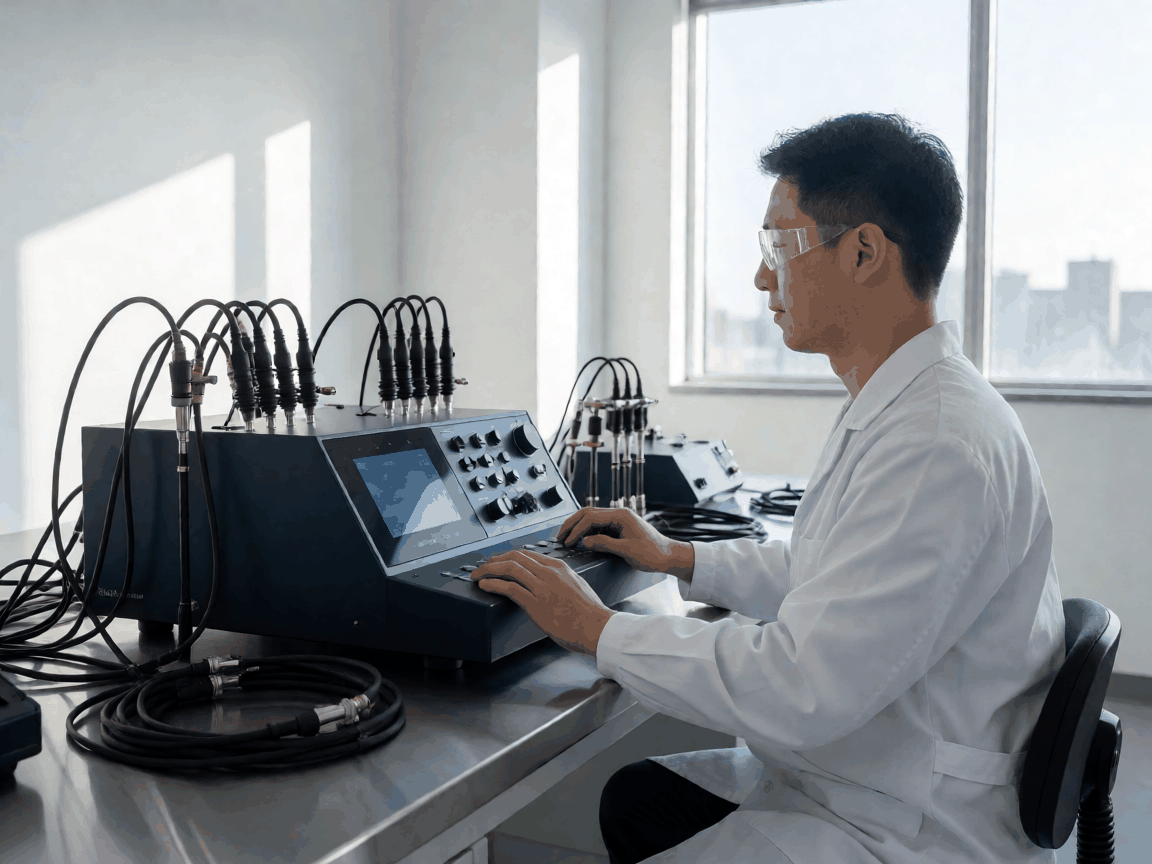
Another recurring cost is handler‑interface mismatch. Buyers order a "standard" GPIB unit only to discover the timing handshake does not match their sorter's firmware revision. The resulting integration effort averages 40 engineering hours per line, and the workaround often introduces measurement jitter that forces a wider guard band, lowering yield.
How It Performs in Use
On the production floor, the critical metric is repeatability at the test frequency used for qualification. A custom unit with a direct‑digital‑synthesis (DDS) source holds frequency error below 10 ppm across the full range, whereas a typical PLL‑based source drifts 50–100 ppm when switching between 1 kHz and 100 kHz. That stability translates directly into a tighter Cp‑D correlation plot, reducing the number of false‑fail parts that must be manually re‑measured.
Temperature stability is the second lever. The custom bridge uses a temperature‑compensated reference capacitor network matched to within 0.1 ppm/°C. In a 23 °C ±5 °C environment, the bridge maintains its calibrated accuracy without daily re‑zeroing. Standard units require a zero‑calibration cycle every shift, adding 15 minutes of downtime per station.
Construction Method and Its Effect on Consistency
The bridge circuit is built on a four‑layer FR‑4 stack with dedicated ground and guard planes. Guard traces surround the high‑impedance nodes, reducing leakage current to below 10 fA. Component selection follows a derating rule: every resistor operates at ≤25% of its rated power, every capacitor at ≤50% of its voltage rating. This margin eliminates the parametric drift that causes the 40–60 ppm/°C creep seen in cost‑optimized designs.
Enclosure machining uses a single CNC setup for all mounting features, guaranteeing that rack‑mount ears and handler‑interface cutouts align within 0.15 mm across the lot. This dimensional control prevents the misalignment that forces buyers to shim or re‑drill panels during integration.
Where This Product Beats Standard Alternatives
Standard Off‑the‑Shelf Bridge
- Fixed frequency set (typically 3–5 points)
- Internal bias limited to 30 V
- Single handler interface (GPIB or USB)
- Calibration interval 12 months, no burn‑in data
- Temperature coefficient ±20 ppm/°C (typical)
Custom Advanced Bridge
- Programmable frequency 20 Hz – 2 MHz
- External bias input up to 200 V
- Multiple handler interfaces simultaneously
- Calibration interval 24 months with burn‑in report
- Temperature coefficient ≤5 ppm/°C (guaranteed)
The custom bridge eliminates the guard‑band inflation that standard units force. When a buyer can specify the exact frequency points and bias levels their qualification plan requires, the test sequence shortens by 30–40% because fewer frequency‑change settling delays occur. The tighter temperature coefficient also means the same test limit can be applied year‑round without seasonal re‑qualification.
Usage Scenarios and Buyer Segments
Production‑line incoming inspection of MLCC reels demands high throughput and handler integration. The custom bridge's sub‑millisecond measurement speed at 100 kHz and deterministic handler handshake keep the test cell cycle time under 200 ms. R&D labs characterizing new dielectric materials need the wide frequency sweep and high bias voltage to map C‑V curves up to 200 V. Both segments benefit from the same hardware platform; only the firmware configuration and interface complement change.
Academy and training facilities purchasing for teaching labs prioritize ruggedized enclosures and simplified front‑panel operation. They typically order the portable variant with a built‑in battery option and a reduced‑function firmware load that locks out advanced settings, preventing accidental configuration changes during student labs.
Segment-Specific Requirements
Brand product managers integrating the bridge into automated test equipment (ATE) require a documented SCPI command set, deterministic latency figures, and a 1U rackmount footprint with front‑panel service access. They also need a calibration certificate traceable to a national metrology institute, delivered with each unit, and a spare‑parts kit covering the reference capacitor network and the DDS synthesizer module.
Club or academy purchasing managers focus on total cost of ownership: a three‑year warranty with on‑site calibration service, a rugged carry case rated for IP54 transit, and a firmware update mechanism that does not require a PC connection. These requirements drive the choice of the portable enclosure variant and the inclusion of a micro‑SD slot for field updates.
What Gets Checked Before Shipment
Every unit undergoes a 48‑hour burn‑in at 40 °C while cycling through all programmed frequencies and bias levels. Functional verification includes a full accuracy sweep against a calibrated standard capacitor bank at 1 kHz, 10 kHz, and 100 kHz. The test record captures Cp, D, and phase angle at each point; deviation must stay within ±0.02% of the certified value.
Handler interface timing is validated with a simulated sorter load, confirming that the EOM (end‑of‑measurement) pulse width and polarity match the buyer's specification. Cosmetic inspection checks for front‑panel scratch depth ≤0.05 mm and label adhesion per ASTM D3359 method B. Units that pass receive a tamper‑evident calibration seal and a unique serial number linked to the test data archive.
Request a calibration‑verified sample unit to evaluate integration into your test cell.
Request Sample


