custom transformer tan delta test set factory: Specification, Ordering and Quality Notes
Weight and stiffness trade off against each other in a tan delta test set because the high-voltage transformer, the reference capacitor, and the shielding required for sub‑milliwatt loss measurements all add mass, yet the unit must remain portable enough for substation floor work. A factory that customises these sets starts by locking the voltage class — typically 10 kV or 12 kV rms — and the maximum test current, since those two parameters dictate the core cross‑section, the insulation thickness, and ultimately the shipping weight that a two‑person crew can handle without a crane.
Repeat loading drives the failure mode in the high‑voltage lead assembly and the interlock switchgear; every time a test engineer connects a 200 MVA transformer, the cable terminations see mechanical stress and partial‑discharge inception voltage that degrades silicone rubber boots faster than the spec sheet suggests. The limiting factor is rarely the headline tan delta accuracy (±0.0005) but the stability of that accuracy after 500 connection cycles, a temperature swing from −20 °C to +50 °C, and the inevitable knocks during transport.
Scope of Supply and Physical Form
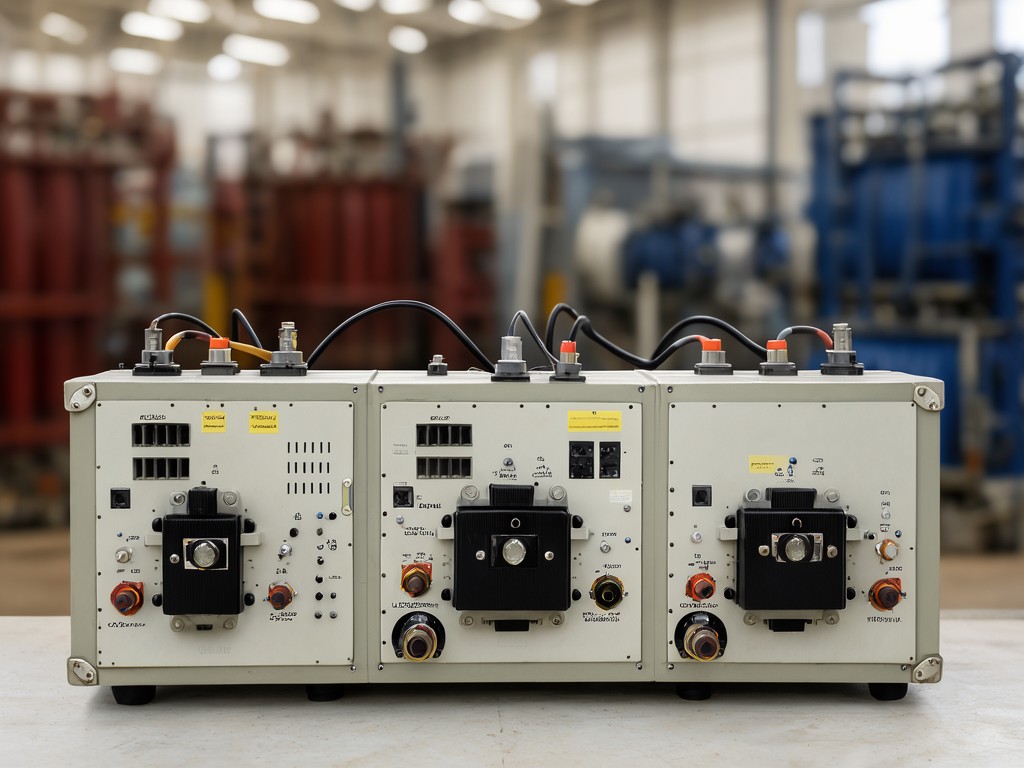
A custom set ships as a single integrated console on lockable castors, containing the HV transformer, the reference standard capacitor (usually a compressed‑gas type for long‑term stability), the measuring bridge, and the industrial PC running the acquisition software. The front panel carries only the essential hardware: a keyed HV‑on switch, an emergency‑off mushroom, a digital voltage display, and a USB port for firmware updates. All high‑voltage connections exit through a dedicated gland plate at the rear, with colour‑coded, keyed receptacles for the test lead, the guard lead, and the ground return. The enclosure is rated IP54 when closed; open‑door operation drops to IP20, so the factory documents the exact clearance required around the console for safe operation in a crowded switchyard.
- Console dimensions: 600 mm W × 800 mm D × 1100 mm H (typical 10 kV unit)
- Mass: 180–260 kg depending on voltage class and optional internal UPS
- HV output: 0–12 kV rms continuously adjustable, 200 mA short‑circuit current
- Reference capacitor: 1000 pF ±0.1 %, gas‑filled, temperature coefficient <5 ppm/°C
- Measurement range: tan δ 0–100 %, capacitance 10 pF–1 µF, resolution 0.0001 tan δ, 0.1 pF
- Power input: 1‑phase 230 V ±10 %, 50/60 Hz, 3 kVA max
Design Constraints Behind the Specification
Critical Specification Rule
The reference capacitor’s temperature coefficient dominates the system’s long‑term accuracy budget. A 5 ppm/°C capacitor drifting 15 °C during a three‑hour test introduces a tan delta error of 0.00075 — larger than the bridge’s own specification. Always confirm the capacitor’s thermal mass and whether the factory fits an active temperature stabilisation jacket.
The bridge topology is fixed as a high‑voltage Schering bridge with active null detection; the customisation space lies in the ratio arms, the detector bandwidth, and the software correction algorithms. A buyer who specifies “IEEE C57.12.90 compliance” without stating the exact test voltage and frequency range forces the factory to over‑design the ratio‑arm resistors for a worst‑case 12 kV/60 Hz scenario, adding 15 kg of resistor bank and doubling the calibration time. Narrow the voltage band to the actual transformer fleet — e.g., 8 kV ±10 % at 50 Hz — and the factory can select a lighter resistor network, reduce the calibration points, and still meet the standard’s accuracy clause.
What Actually Determines Performance
| Parameter | Typical Range | Failure Mode if Exceeded | Factory Verification Method |
|---|---|---|---|
| HV transformer partial discharge | <5 pC at 1.2× rated voltage | Noise floor rises, masking true tan δ | IEC 60270 PD measurement on each unit |
| Ratio‑arm resistor stability | ±10 ppm/°C, ±50 ppm/1000 h | Calibration drift >0.001 tan δ | Temperature cycling −10 °C to +50 °C, 10 cycles |
| Reference capacitor loss tangent | <0.00005 at 10 kV | Systematic offset in all readings | Comparison traceable to national lab standard |
| Interlock circuit response time | <50 ms from door open to HV off | Personnel safety hazard | Simulated fault injection, 1000 operations |
Material Options and Their Trade-offs
Standard Console: Powder‑Coated Mild Steel
Cost baseline. Adequate for indoor substation use where the console stays on a pallet jack. The 2 mm sheet steel provides sufficient shielding for the bridge electronics, but the coating chips at the gland‑plate edges after repeated cable insertion, exposing substrate to corrosion in humid climates.
Add 12 kg over the aluminium option. No extra lead time.
Upgraded Console: Marine‑Grade Aluminium (5083‑H116)
Preferred for utility fleets that move sets between outdoor yards and offshore platforms. The alloy resists salt‑spray corrosion without touch‑up, and the 3 mm skin saves 12 kg versus steel while maintaining the same shielding effectiveness. Machining the gland‑plate cut‑outs takes two extra CNC set‑ups, adding three working days to the build schedule.
Cost premium ≈18 % on the enclosure line item.
Assumptions Buyers Should Stop Making
“The factory can just change the software to read out in percent instead of per‑unit.” The acquisition software is locked to the bridge’s FPGA firmware; changing the display scaling requires a full regression test on the null‑detector linearity, a new calibration certificate, and a firmware version bump that invalidates any existing type‑test report. Budget two weeks and a re‑calibration fee if the unit has already left the factory.
“We’ll use our own 20 m HV test leads to save money.” Lead capacitance and dielectric loss become part of the measurement circuit above 5 kV. The factory’s calibrated lead set is characterised at 0.1 pF/m and tan δ <0.0002; a generic cable typically runs 0.3 pF/m and tan δ 0.001, which swamps the transformer’s own loss signal. The factory will refuse to sign the FAT report with un‑characterised leads.
“A single FAT at the factory covers us for site acceptance.” Site acceptance must verify the interlock chain with the actual substation earthing layout and confirm that the console’s EMC emissions do not trip the station’s protection relays. The factory provides a site‑acceptance checklist, but the test engineer must run it on‑site with the station’s own ground grid.
How Consistency Is Held Across Batches
Every batch of five units shares a single reference capacitor that cycles through the production line as the golden standard. The capacitor’s tan delta and capacitance are measured before the first unit, after the third, and after the fifth; if the drift exceeds 0.00002 tan δ or 0.05 % capacitance, the batch is halted and the capacitor is re‑conditioned in the laboratory oven. This moving‑reference method catches resistor‑bank ageing and detector‑gain drift that a single‑point calibration would miss.
The HV transformer windings are wound on the same mandrel using wire from the same reel lot. After vacuum pressure impregnation, each transformer undergoes a 1.5× rated voltage withstand for 60 seconds and a partial‑discharge scan at 1.2× rated voltage. The PD inception voltage must exceed 1.3× rated voltage with a magnitude below 5 pC. Units that pass are serialized and the PD waveform stored in the factory’s traceability database for the warranty period.
Capacity, Tooling and Scheduling
| Order Profile | MOQ | Lead Time (ex‑works) | Tooling Charge |
|---|---|---|---|
| Standard 10 kV console, steel enclosure, factory firmware | 1 unit | 6–8 weeks | None |
| Custom voltage class (e.g., 15 kV) or aluminium enclosure | 2 units | 10–12 weeks | €3,500 for HV transformer redesign |
| Private‑label firmware, custom report templates, branded UI | 3 units | 12–14 weeks (includes software V&V) | €7,000 for firmware branch + documentation |
| Full OEM: custom enclosure geometry, integrated UPS, special connectors | 5 units | 16–20 weeks (prototype + type test) | €18,000–25,000 depending on mechanical complexity |
Export Packaging and Handling Protection
Each console is bolted to a treated‑timber skid (ISPM‑15 compliant) with four M12 eye bolts for crane lifting. The skid dimensions match the console footprint plus 100 mm clearance on all sides. A vacuum‑sealed barrier bag with desiccant (3 units per cubic metre) encloses the console before the outer plywood crate is screwed shut. Shockwatch 25 G indicators are affixed to two opposite corners; if either triggers, the factory requires a full re‑calibration before commissioning.
The HV test leads ship in a separate, foam‑lined flight case with individual compartments for the test lead, guard lead, and ground return. Connector caps are tethered to the case to prevent loss. The reference capacitor travels inside the console, but its calibration certificate and the national‑lab traceability paperwork are duplicated in a sealed document pouch attached to the crate exterior for customs inspection.
Request a Sample Configuration Review
Submit your voltage class, transformer fleet profile, and preferred enclosure material. The factory will return a marked‑up specification sheet, a preliminary FAT plan, and a firm lead‑time quote within five working days.
Start the specification review →


