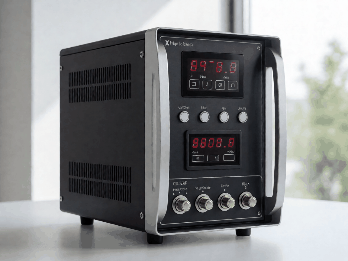
Specifying top quality high voltage switch tester control power supply exporter for Wholesale and OEM Orders
Fatigue appears at the stress concentration where a budget power supply meets a high-voltage switch tester's inrush profile. The tester draws sharp, repetitive current spikes during contact timing and resistance measurement cycles. A control supply that sags or rings under those transients feeds timing errors into the test report — errors the end user cannot see until a breaker fails in service.
Procurement teams qualifying a second source typically discover the gap during burn-in: the replacement unit passes static load regulation but drifts 150 mV on the 24 V rail when the tester fires a 15 A pulse at 50 Hz. That drift moves the tester's internal reference, shifting contact-time readings by 0.3 ms. In a 12 ms operate window, 0.3 ms is the difference between pass and fail.
Where Cheaper Alternatives Fall Short
Repeat loading drives the failure in three places the datasheet rarely quantifies. First, the input filter's X-capacitors degrade under continuous high-dV/dt switching noise from the tester's own inverter stage. Second, the output electrolytics see ripple current at twice the line frequency plus the tester's pulse repetition rate; 105 °C rated caps still dry out in 18 months if the ESR spec was written for sinusoidal ripple, not square-edge pulses. Third, the control IC's gate-drive supply collapses during a 200 A/μs load step because the auxiliary winding was sized for steady state.
Buyers report the same pattern: units pass incoming inspection, run clean for three months, then start tripping the tester's over-voltage latch during weekend unattended runs. Root cause traces to a 0.1 %/°C drift in the feedback divider — acceptable for industrial DIN-rail supplies, fatal for a tester that calibrates at 0.05 % accuracy.
Design Constraints Behind the Specification
The limiting factor is rarely the headline specification. A 300 W, 24 V/12.5 A supply sounds straightforward until the tester manufacturer hands over the transient profile: 0→15 A in 2 μs, 50 Hz burst for 200 ms, then 2 A steady for 3 s. The control loop must cross 0 dB below 1/5th the pulse repetition frequency to avoid sub-harmonic oscillation, yet the error amplifier needs 60 dB gain at DC for 0.05 % load regulation. Those two requirements pull compensation in opposite directions.
Mechanical constraints add another layer. The tester chassis allocates 180 × 95 × 45 mm for the supply. That volume forces a two-board stack: main converter on the bottom, filter and connector board on top. Thermal coupling between boards means the output capacitors sit 8 mm above the primary MOSFETs. Without a dedicated airflow path, cap temperature rides 12 °C above ambient at full load — cutting rated life in half unless the cap selection accounts for it.
What Actually Determines Performance
Transient Response
< 2 % deviation, < 50 μs recovery for 0→15 A step. Measured at tester's sense terminals, not supply output terminals.
Ripple & Noise
< 50 mVpp (20 MHz BW) including common-mode. Critical for tester's analog front-end SNR.
Hold-up Time
≥ 20 ms at full load, 85 VAC input. Allows tester to complete measurement cycle during line dip.
Isolation Margin
4 kVAC primary-secondary, 1.5 kVAC primary-PE. Tested 100 % at final, not type-test only.
These four parameters interact. Tightening transient response by increasing control bandwidth raises conducted EMI, which forces a larger input filter — eating board space and adding thermal mass. The specification negotiation is a trade-off matrix, not a checklist.
Option Comparison by Usage Level
| Parameter | Lab / Intermittent Use | Production Line Continuous | Unattended Field Deployment |
|---|---|---|---|
| Topology | LLC resonant, fixed frequency | Phase-shifted full-bridge, variable frequency | Dual-active-bridge with pre-regulator |
| Output Capacitors | Polymer electrolytic, 5000 h @ 105 °C | Hybrid: polymer + ceramic bank, 10 kh @ 105 °C | All-ceramic, 20 kh @ 125 °C, derated 50 % |
| Feedback Scheme | Optocoupler, TL431 | Digital isolator + MCU, programmable loops | Digital isolator + FPGA, adaptive compensation |
| Thermal Management | Conduction to chassis, no fan | Integrated 40 mm PWM fan, speed monitored | Heat-pipe to external cold plate, fanless |
| Typical Unit Cost (100 pcs) | $85–$110 | $145–$190 | $260–$340 |
| Lead Time (after drawing approval) | 4–5 weeks | 6–7 weeks | 8–10 weeks |
The cost steps reflect component derating margins and validation depth. Field-deployment units undergo 500-hour burn-in at 50 °C ambient with programmed load transients every 30 seconds. Production-line units get 100-hour burn-in at 40 °C. Lab units receive 24-hour functional test only.
Requirements by Buyer Segment
Importers supplying utility test labs need traceability to IEC 61010-1 and IEC 61557. They require a Certificate of Conformity per batch, not per order, and they audit the component substitution log quarterly. Their MOQ is typically 50 units but they buffer 10 % safety stock at their regional warehouse.
Procurement officers at switchgear OEMs prioritize supply continuity over unit price. They lock a 12-month rolling forecast with quarterly firm orders. Their qualification package includes a first-article inspection report (FAIR) per AS9102 Form 1-3, even though the product isn't aerospace — they use the format because it forces dimensional, material, and functional verification on every critical characteristic.
Distributors serving field-service contractors need ruggedized packaging and a 3-year advance-replacement warranty. They also require the supply to carry the tester OEM's branding, not ours. That means silk-screen artwork approval happens at the same gate as electrical spec freeze — any change after that gate triggers a new FAIR.
Inspection Items and Test Methods
| Inspection Item | Method | Acceptance Criteria | Frequency |
|---|---|---|---|
| Input/Output Hi-pot | 4 kVAC 60 s, ramp 500 V/s, leakage < 5 mA | No breakdown, leakage ≤ 3 mA | 100 % final test |
| Load Regulation (DC) | Electronic load, 0–100 % in 10 % steps, sense at tester terminals | ≤ 0.05 % Vout | 100 % final test |
| Transient Response | Programmable load, 0→15 A, 2 μs rise, 50 Hz burst capture | Peak deviation ≤ 2 %, settling ≤ 50 μs | Type test + 10 % batch audit |
| Ripple & Noise | 20 MHz BW, 0.1 μF ceramic + 10 μF tantalum at probe tip | ≤ 50 mVpp differential, ≤ 100 mVpp common-mode | 100 % final test |
| Thermal Cycling | -20 °C to +70 °C, 15 min soak, 5 °C/min ramp, 100 cycles | No parametric shift > 2 × initial tolerance | Qualification + periodic re-qual |
| EMI Conducted | CISPR 22 Class B, LISN, 150 kHz–30 MHz | ≥ 6 dB margin at all frequencies | Type test |
| MTBF Demonstration | Accelerated life: 50 °C, full load, 1000 h, Weibull analysis | Calculated MTBF ≥ 200 kh @ 25 °C, 90 % confidence | Design validation only |
Batch audit samples pull from the middle of the production run, not the start or end. The audit includes a 4-hour thermal soak at 50 °C with the actual tester load profile. Units that pass audit ship; units that fail trigger a 100 % re-screen of the batch.
Export Packaging and Handling Protection
Each unit ships in a custom-molded ESD-safe clamshell (surface resistance 10⁶–10⁹ Ω) that cradles the supply at four mounting-hole locations. The clamshell sits inside a double-wall corrugated carton (ECT 48) with 50 mm PE foam end caps. Carton dimensions: 320 × 210 × 130 mm. Gross weight per carton: 3.2 kg (single unit) or 12.8 kg (4-unit master carton).
Palletization follows ISPM-15 heat-treated wood. Master cartons stack 5 layers × 8 per layer = 40 units per pallet. Stretch-wrap includes a humidity indicator card (30/40/50 % RH) and a ShockWatch 25G label. Ocean freight containers are loaded with desiccant strips (2 kg per 20 ft container) and temperature loggers set to alarm above 60 °C.
Labeling per buyer spec: barcode (Code 128) with serial number, batch code, manufacturing date, and revision letter. Country of origin marked on carton and unit. No plastic strapping directly on cartons — edge protectors mandatory.
Care, Storage and Service Life
Shelf life in original packaging: 24 months at ≤ 30 °C, ≤ 60 % RH. Beyond 24 months, electrolytic capacitors require reforming — apply rated voltage through a 1 kΩ resistor for 30 minutes before commissioning. Units stored without power for > 6 months should receive a 2-hour burn-in at 50 % load before entering service.
In service, the dominant wear-out mechanism is output capacitor ESR rise. Monitor the tester's reported supply voltage under pulse load; a 20 % increase in voltage droop versus commissioning baseline indicates capacitor end-of-life. Fan-bearing wear (production-line variant) shows as audible tone change or speed-report deviation > 15 % from baseline.
Preventive maintenance schedule: annual visual inspection for discoloration, connector pin oxidation, and fan blade dust buildup. Clean with dry compressed air (≤ 3 bar) only — no solvents on conformal coating. Re-torque terminal block screws to 0.5 N·m after first thermal cycle. Replace output capacitor bank at 70 % of rated hours (7,000 h for polymer, 14,000 h for hybrid, 20,000 h for all-ceramic) regardless of apparent condition.
Request a Quotation Review
Send the tester's transient profile, mechanical envelope drawing, and your annual volume forecast. We return a marked-up specification with component selections, a FAIR template, and a sample-build schedule within 5 business days.
Start the qualification package →


