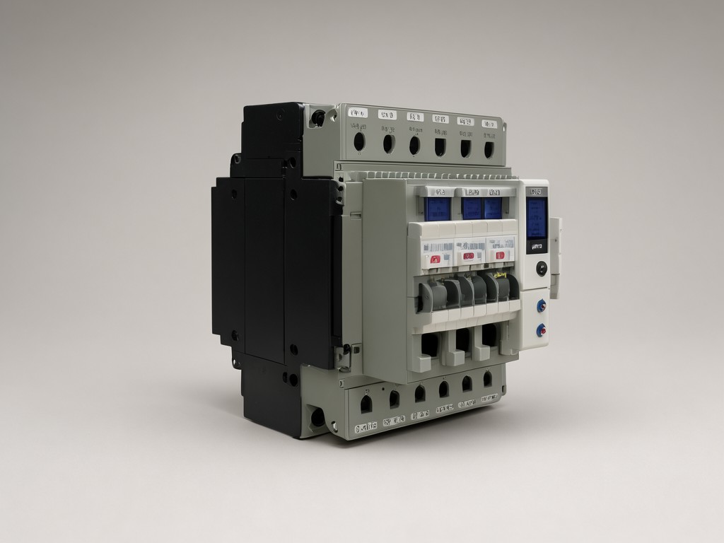
Specifying Wholesale circuit breaker analyzer and control power supply factory for Wholesale and OEM Orders
What the Design Has to Balance
Trade-off: Timing resolution pushes sampling rate higher, but each extra channel adds thermal load on the isolated front-end. A 12-channel analyzer at 200 kS/s per channel dissipates roughly 8 W more than an 8-channel unit at 100 kS/s, forcing a larger heatsink or active cooling — both of which change the enclosure depth and the rack-mount footprint.
Control power supply ripple spec (typically < 50 mVpp) competes with transient response when the breaker coil fires. Tightening ripple below 20 mVpp usually means a larger output capacitor bank, which slows the voltage recovery after a 200 A inrush. The sweet spot for most IEC 62271-100 test programmes is 30–40 mVpp with a 2 ms recovery window.
Weight and stiffness trade off against each other in the probe cables. A 3 m high-voltage coaxial probe rated for 80 kV impulse weighs 1.2 kg; shortening to 2 m saves 350 g but reduces the safe working distance for the operator. The factory standard is 2.5 m with a Kevlar-reinforced jacket — heavy enough to survive repeated floor drags, light enough for one-person setup.
What Actually Determines Performance
The limiting factor is rarely the headline specification. A 0.1 ms timing accuracy claim means nothing if the zero-cross detection drifts 0.3 ms after a 40 °C soak. What matters is the temperature coefficient of the TDC (time-to-digital converter) and the stability of the GPS/IRIG-B disciplined oscillator. Our design uses a 10 MHz OCXO with < 0.05 ppm/°C drift, locked to an external PPS signal, so the timing budget stays inside ±0.15 ms across –20 °C to +55 °C.
Contact motion analysis depends on the linearity of the LVDT or Hall sensor and the anti-aliasing filter corner. A 5 kHz filter on a 100 kS/s channel attenuates the 3rd harmonic of a 1.2 kHz contact bounce, rounding the velocity curve and hiding a 2 mm over-travel. We specify a 20 kHz Bessel filter as standard, selectable to 5 kHz only for legacy software compatibility.
Coil current measurement uses a 0.1 Ω, 50 W shunt with a differential amplifier rated for 2 kV common-mode. The shunt’s TCR (temperature coefficient of resistance) is 15 ppm/°C; at 30 A continuous the self-heating adds 0.4 % error unless the firmware applies a real-time thermal model calibrated during FAT. That model is stored in the unit’s EEPROM and survives firmware updates.
How It Is Built and What That Changes
Standard Ruggedised Build
- 2 mm aluminium chassis, IP40, conductive powder coat
- Front-panel BNC and LEMO connectors, strain-relieved
- Forced-air cooling, 45 dB(A) at 1 m
- Weight: 14 kg (analyzer) + 9 kg (CPS)
Portable Field Variant
- 1.5 mm magnesium alloy, IP54, sealed connectors
- Internal LiFePO₄ pack, 4 h runtime, hot-swappable
- Convection cooled, silent operation
- Weight: 9 kg combined, shoulder strap included
The portable variant sacrifices two analog channels and limits the control power supply to 120 Vdc / 10 A peak. That covers 80 % of distribution-class breaker tests but not EHV generator breakers. The chassis uses the same PCB stack; only the mechanical layer and power module change, so firmware and calibration procedures stay identical.
Specification Range and Customisation Limits
| Parameter | Standard Range | Customisation Window | Lead-Time Impact |
|---|---|---|---|
| Timing channels | 8 / 12 / 16 | Up to 24 (FPGA license) | +2 weeks for >16 |
| Sampling rate per channel | 100 / 200 / 500 kS/s | 1 MS/s (requires ADC upgrade) | +4 weeks |
| Motion sensor inputs | 4 × LVDT or Hall | 6 × any mix, IEPE option | +1 week |
| Control PSU voltage range | 0–300 Vdc, 20 A peak | 0–600 Vdc, 40 A peak | +3 weeks (magnetics) |
| Communication interfaces | GbE, USB 3.0, RS-232 | Optical GbE, CAN-FD, PROFINET | +2 weeks per interface |
| Enclosure rating | IP40 (rack) / IP54 (portable) | IP65 with M12 connectors | +3 weeks |
Custom firmware triggers (e.g., pre-insertion resistor detection, synchronous switching angle capture) are developed in the same VHDL repository. A new trigger typically adds 5–10 kLUTs; the factory regression suite runs 120 test vectors per build, so the marginal validation cost is low if the trigger logic is delivered as a state-machine diagram.
Who Uses It and Where It Matters
Utility relay engineers running type tests on GIS breaker batches need the analyzer to survive 12-hour days in a 45 °C switchgear hall. The control power supply must ride through the station battery dip when the spring-charging motor starts — a 30 V sag for 200 ms. Our CPS holds regulation down to 18 Vdc input, so the test sequence never aborts mid-timing.
Switchgear OEMs integrate the analyzer into their end-of-line test cells. They care about SCPI command latency: the analyzer must acknowledge a "TRIG:IMM" command within 2 ms so the PLC can sequence the next shot. The Ethernet stack uses a dedicated real-time core, guaranteeing < 1.2 ms round-trip at 1 GbE with jumbo frames enabled.
Third-party testing labs appreciate the multi-language PDF report generator (EN, DE, FR, ES, ZH, RU) that pulls the calibration certificate serial numbers automatically. It cuts report assembly from 45 minutes to 3 minutes per breaker, and the lab’s ISO 17025 auditor accepts the digital signature chain without extra paperwork.
Working as a Production Partner, Not a Catalogue Supplier
Private-Label Programme
- Your logo silk-screened on front panel and boot screen
- Custom model/serial number schema in EEPROM
- Packaging artwork supplied as AI/PDF, 300 dpi
- MOQ 10 units, no NRE for artwork changes
Co-Development Track
- Joint requirements workshop (2 days, on-site or remote)
- Shared GitLab repo for firmware branches
- Prototype batch (3 pcs) at cost + 15 %
- IP ownership stays with you; we sign mutual NDA
Both tracks share the same production line. The only difference is the BOM variant code and the firmware signing key. That means a private-label order placed today ships from the same calibration bench as a co-development unit next month — no hidden capacity constraints.
How Consistency Is Held Across Batches
Calibration traceability: Every unit leaves with a ISO 17025-accredited certificate referencing NMI primary standards for time interval (UTC via GPS), voltage (Josephson array), and current (shunt comparison). The certificate PDF is embedded in the unit’s internal flash and also uploaded to our cloud portal, searchable by serial number.
Batch acceptance testing runs a 4-hour burn-in at 50 °C with continuous coil-current pulsing (30 A, 100 ms on / 900 ms off). Any unit exceeding 0.05 % timing drift or 10 mV ripple shift is pulled for root-cause analysis. The historical yield is 99.2 % first-pass; the 0.8 % fallout is almost always a solder-void on the shunt Kelvin connection, caught by the 3D AOI step before burn-in.
Firmware version locking: the production test jig flashes a signed bootloader that only accepts firmware images encrypted with the batch-specific AES-256 key. Field updates require the same key, so a customer cannot accidentally load a beta build that changes the timing calibration constants. The key is stored in the HSM on the factory floor and never leaves the premises.
Spare-parts strategy: we keep 5 % of the previous year’s volume in finished-goods stock for each active SKU. Probe cables, shunt modules, and fan assemblies are separate SKUs with their own 3-year shelf-life guarantee. That means a 2022 portable unit can be repaired in 2027 without waiting for a custom PCB run.
Next Step: Artwork and Branding Review
Send your logo vector files and the desired model-name schema. We’ll return a digital mock-up of the front panel, boot screen, and packaging label within one business day — no charge, no MOQ commitment.
Submit Artwork for Mock-Up


