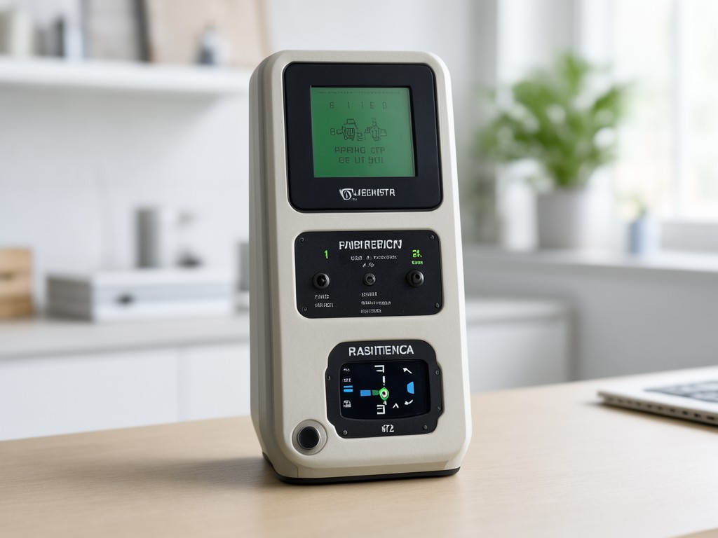
Specifying factory direct earth resistivity impedance tester top supplier for Wholesale and OEM Orders
The Problem Buyers Keep Paying For
Field crews return units with cracked enclosures, corroded banana jacks, and display delamination after one wet season. The root cause is rarely the measurement electronics — it's the mechanical integration decisions made during enclosure assembly and connector overmolding. A tester rated IP67 on the datasheet fails at the cable gland because the gland spec was written for static panel mount, not the daily flex of a trailing electrode cable across rocky terrain.
Buyers who specify only measurement accuracy and frequency range end up managing warranty returns instead of deploying crews. The cost of a single failed grounding survey — remobilization, delayed permit approval, client penalty clauses — exceeds the unit price by 20x. Consistency in sealing, strain relief, and button tactile response across production lots is what prevents that cycle.
Complaint-Prevention Matrix
| Field Condition | Recurring Failure | Design Specification |
|---|---|---|
| Daily electrode cable flex, 50+ cycles per survey day | Banana jack solder joint fatigue, intermittent contact at 2-3 months | Overmolded strain relief with 15 mm bend radius, jack potted to PCB |
| Rain, mud, groundwater immersion to 0.5 m | Display fogging, membrane switch delamination, battery compartment corrosion | Optical bonding display to front bezel, silicone gasket groove with 25% compression, conformal coat PCB |
| Temperature swing -20 °C to +50 °C in vehicle cab | LCD contrast drift, battery capacity loss, enclosure warping at mounting bosses | Temperature-compensated LCD bias circuit, LiFePO4 pack with BTE, 30% glass-filled PA66 enclosure |
| Gloved operation, 8-10 hour shifts | Membrane switch actuation failure, tactile click loss, accidental multi-press | Tactile metal domes 3.5 N actuation force, 1.2 mm travel, raised bezel guard |
| Rough handling, drop from 1 m onto compacted gravel | Corner cracks at PCB mount points, BNC connector shear-off | Internal shock mounts for PCB, BNC flange bonded to enclosure wall with structural adhesive |
Size, Weight and Specification Range
The form factor is dictated by the electrode cable management system. A unit that carries 400 m of multi-conductor cable on an integrated reel adds 3.2 kg and 85 mm depth versus a terminal-block-only variant. Buyers ordering for helicopter-supported surveys need the reel-less configuration; road-accessible utility crews prefer the integrated reel. Both share the same front-panel layout and firmware branch.
Weight distribution matters more than total mass. A 4.8 kg unit with the battery pack centered behind the display balances in one hand. The same mass with batteries in a lower compartment creates a 120 mm moment arm that fatigues the wrist inside two hours. We fix the battery location relative to the display hinge line across all configurations.
| Parameter | Compact Terminal-Block Unit | Integrated Reel Configuration | Tolerance / Consistency Target |
|---|---|---|---|
| Length × Width × Depth (mm) | 285 × 210 × 95 | 285 × 210 × 180 | ±1.5 mm per dimension, lot-to-lot |
| Weight with batteries (kg) | 4.2 | 7.4 | ±0.15 kg, ±5 mm CG location |
| Display: transflective LCD, diagonal (inch) | 4.3 | 4.3 | Same panel, same optical bond process |
| Operating temperature (°C) | -20 to +50 | -20 to +50 | Validated at extremes per lot |
| IP rating (enclosure closed) | IP67 | IP67 | 100% pressure decay test at 30 kPa |
| Battery chemistry | LiFePO4, 12 Ah | LiFePO4, 24 Ah | Cell lot traceability to manufacturer date code |
| Electrode connectors | 4 × overmolded banana, 1 × BNC | 10 × overmolded banana on reel, 1 × BNC | Pull test 50 N, 500 cycles per lot sample |
Comparing Two Standard Configurations
The decision between a 4-channel Wenner-only unit and a 10-channel multi-array system is not about measurement capability — both cover the same resistivity range and frequency span. It's about crew size, daily setup time, and whether the client's scope requires dipole-dipole or pole-pole arrays for lateral resolution.
4-Channel Wenner Configuration
Single four-electrode sequence per measurement. Crew of two: one at the instrument, one moving the potential electrodes. Typical day — 25 soundings to 50 m depth. Setup time per station: 3 minutes. No array switching in firmware. Firmware branch locked to Wenner geometry; no dipole-dipole license key to manage.
Best fit: Resistivity profiling for grounding design, corrosion assessment, shallow aquifer mapping. Private-label buyers targeting electrical contractors and small geotechnical firms.
10-Channel Multi-Array Configuration
Ten electrode takeouts support Wenner, Schlumberger, dipole-dipole, pole-pole, and pole-dipole without rewiring. Crew of three: instrument operator, two electrode teams leapfrogging. Typical day — 40 soundings with automatic array sequencing. Firmware includes all array geometries; license key enables advanced inversion export.
Best fit: Detailed subsurface imaging, archaeological survey, contaminant plume delineation. Private-label buyers targeting geological survey companies and environmental consultancies.
Assumptions Buyers Should Stop Making
"IP67 means it survives rain." The rating applies to the closed enclosure with all port caps seated. In practice, crews leave the USB-C port open for data offload between soundings. A single droplet on the CC pins triggers a corrosion cascade that kills the charge pump for the current injector within weeks. Specify a tethered cap with a lanyard short enough to stay clear of the electrode cables.
"Accuracy spec covers the whole system." The datasheet accuracy (±2% of reading ±0.01 Ωm) is for the instrument alone, measured with a precision resistor box at 23 °C. Add 200 m of 16 AWG electrode cable with field splices, contact resistance at the stakes, and telluric noise — the effective uncertainty balloons to ±8-12%. Buyers who need ±3% system accuracy must specify cable sets with characterized resistance and four-point stake adapters, not just the instrument.
"Firmware updates are free and universal." The Wenner-only hardware lacks the FPGA resources for dipole-dipole current waveform synthesis. A firmware key cannot unlock what the silicon cannot do. Confirm the hardware SKU matches the array requirements before issuing the PO.
Requirements by Buyer Segment
Electrical contractors bidding utility grounding jobs need the compact unit with a 5-year calibration certificate traceable to NMI, a hard-shell case that fits in a service truck drawer, and a firmware lock that prevents accidental array changes. They order 15-30 units per release, branded with their logo on the bezel and the case lid.
Geological survey companies running multi-client campaigns need the 10-channel system with GPS-tagged data, automatic coordinate transformation to local grid, and a ruggedized tablet mount on the enclosure lid. They order 5-10 units but require a 30-day evaluation loaner before committing. Their artwork package includes boot-screen animation and custom report templates.
Mineral exploration drillers need a borehole logging variant — same electronics, slim 85 mm diameter pressure housing rated to 500 m, with a winch-mounted depth encoder interface. This is a mechanical derivative, not a firmware variant. MOQ starts at 3 units because the housing machining setup is distinct.
How Consistency Is Held Across Batches
Process choice shows up later as weight drift. The enclosure is injection-molded 30% glass-filled PA66. If the mold temperature controller drifts 5 °C above setpoint, the glass fiber orientation shifts at the boss walls, reducing screw pull-out strength by 18%. We run in-mold pressure sensors on every cavity; any shot outside the 85-92 bar window is quarantined and destructively tested. The data logs travel with the lot paperwork.
The current injector circuit uses a matched JFET pair for the Howland pump. Gain matching is trimmed by laser-cutting a thin-film resistor on the PCB after assembly. The trim target is 0.05% mismatch at 1 kHz. We verify on a 100% basis using a 4-wire Kelvin fixture that injects 10 mA and measures the voltage drop across a 0.1 Ω reference. Units outside ±0.08% are reworked or scrapped — no statistical sampling.
Display optical bonding uses a UV-cure adhesive with a 120-second cure window. The dispense robot path is validated by weight check on every 50th unit; a 3 mg deviation triggers a full line audit. Delamination after thermal cycling (-30 °C / +70 °C, 10 cycles) is the acceptance gate. We keep a reference unit from each production week in the environmental chamber for ongoing monitoring.
Request a Evaluation Unit for Your Private-Label Program
We ship a calibrated, branded sample with your artwork applied — same enclosure, same firmware branch, same lot traceability as production units. Test it in your crew's actual field conditions before committing to a release order.
Request Sample Shipment


