Factory Direct Ground Impedance and Earth Resistance Tester Manufacturer: Specification, Ordering and Quality Notes
Scope of Supply and Physical Form
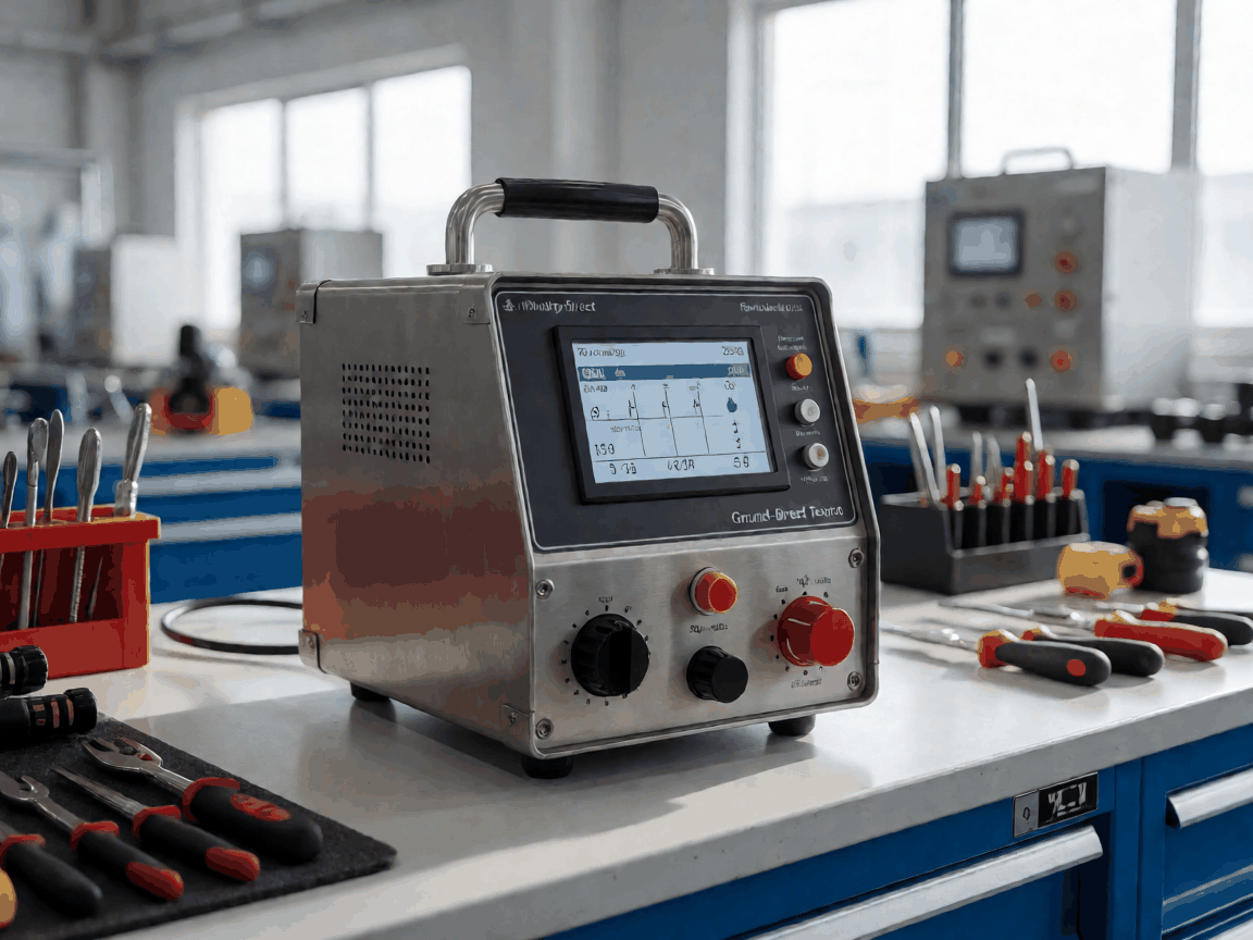
Balance and load analysis shows that a ground impedance tester leaves the factory as a calibrated, self-contained instrument rather than a component kit. The standard shipment includes the main unit, a set of four test leads with colour-coded alligator clips (red, black, green, blue), two auxiliary earth spikes (300 mm stainless steel), a rechargeable lithium-ion pack (typically 7.4 V / 5 Ah), a 100-240 V AC adapter with interchangeable mains plugs, a rugged carry case rated IP67, and a factory calibration certificate traceable to national standards. Private-label buyers can substitute the case foam insert, silk-screen the logo on the enclosure lid, and request a custom boot-screen graphic — all agreed on the pre-production drawing package before tooling commits.
The enclosure is a two-shot mould: glass-filled polycarbonate shell (UL94 V-0) over a TPE over-mould that seals the battery compartment and connector panel to IP65. A hinged bail stand on the rear allows bench-top viewing at 30° or 60°. Weight with battery is 1.8 kg; dimensions 245 × 185 × 95 mm. These figures are fixed for the current platform — any change triggers a new mould trial and a 6-week lead-time extension.
What Actually Determines Performance
The interface between parts determines measurement integrity more than any single component. The front-end uses a four-terminal Kelvin switching matrix driven by a 128 kHz square-wave generator (selectable 94 Hz, 105 Hz, 111 Hz, 128 Hz to avoid mains harmonics). Test current is software-limited to 20 mA rms (open-circuit voltage ≤ 50 V) for CAT IV 600 V safety. Resolution is 0.001 Ω on the 0-20 Ω range, 0.01 Ω on 20-200 Ω, and 0.1 Ω on 200-2000 Ω. Basic accuracy is ±(1.5% rdg + 3 dgt) at 23 °C ± 5 °C after 30-minute warm-up.
Calibration Drift Warning
If the instrument is stored above 50 °C or subjected to >30 g shock (typical drop from 1 m onto concrete), the internal reference resistor can shift by up to 0.2 %. Re-calibration requires a 4-wire decade box traceable to ±0.01 %. We recommend a 12-month calibration interval for daily-use fleets; 24 months for occasional audit teams.
Display is a 4.3" transflective TFT (480 × 272) with LED backlight — readable in direct sunlight without heater. The GUI supports three languages (EN, ES, FR) selectable at boot; additional languages require a firmware rebuild (MOQ 200 units). Data logging: 8 GB internal eMMC, CSV export via USB-C (mass storage class) or Bluetooth 5.0 (SPP profile). Battery life: 14 hours continuous 3-pole measurement at 10-second intervals; 8 hours with Bluetooth active.
Size, Weight and Specification Range
Standard Configuration
- Measurement modes: 3-pole, 4-pole (Wenner), selective clamp, stakeless clamp
- Test frequency: 94 / 105 / 111 / 128 Hz (auto or manual)
- Test current: 20 mA rms max (software limited)
- Resistance range: 0.001 Ω – 2 kΩ (auto-ranging)
- Impedance range: 0.01 Ω – 2 kΩ @ 128 Hz
- Accuracy: ±(1.5% + 3 dgt) on resistance; ±(2% + 5 dgt) on impedance
- Safety: IEC 61010-1 CAT IV 600 V / CAT III 1000 V
- EMC: IEC 61326-1, IEC 61326-2-2
Physical & Environmental
- Dimensions (W×H×D): 245 × 185 × 95 mm
- Weight with battery: 1.8 kg
- Operating temperature: -10 °C to +50 °C
- Storage temperature: -20 °C to +60 °C
- Humidity: 90% RH non-condensing
- Ingress protection: IP65 (lid closed), IP40 (lid open)
- Drop test: 1 m onto concrete (6 faces)
- Battery: 7.4 V / 5 Ah Li-ion, replaceable
- Charge time: 4.5 h from empty
Usage Scenarios and Buyer Segments
Consistency depends on matching the instrument to the service condition. Utility substation crews running monthly fall-of-potential tests on 11 kV earthing grids need the 4-pole Wenner mode with 50 m test leads (optional reel kit, 0.5 kg). Renewable-energy EPC contractors commissioning wind-turbine foundations prefer the selective clamp mode — no need to disconnect the down-conductor, saving 20 minutes per tower. Railway signalling maintainers use the stakeless clamp on bond rails where driving auxiliary spikes is forbidden. Private-label importers targeting the rental market often specify the rubber-booted "yellow" variant (Pantone 109C) for high visibility and request a 3-year warranty extension (adds 4% to unit cost, covers calibration drift and accidental damage).
Distributors serving electrical wholesalers typically order 50-100 units per SKU with standard firmware and a 1-year warranty. National metrology institutes and accredited calibration labs order the "Reference" grade: each unit ships with an ISO 17025 calibration certificate at 5 points per range, and the front-end reference resistor is hand-selected from a 0.005% batch. That grade carries a 12-week lead time and a 35% price premium.
OEM and ODM Programme Structure
The OEM programme has three tiers. Tier 1: badge-only — your logo on the lid, your part number on the rating label, standard firmware, MOQ 50 units, lead time 4 weeks from artwork approval. Tier 2: firmware skin — custom boot screen, menu language subset, default test-profile presets (e.g., "Utility-11kV", "Wind-Turbine"), your USB VID/PID, MOQ 200 units, lead time 8 weeks (includes firmware validation). Tier 3: hardware variant — different connector panel (e.g., 4 mm banana instead of BNC), added hardware filter for high-noise environments, custom carry-case foam, MOQ 500 units, lead time 14 weeks (new mould trial for connector bezel).
ODM projects start with a requirements workshop (remote or on-site). We provide a functional specification document, a mechanical envelope drawing, and a bill-of-materials cost breakdown. You approve the spec, we build 5 engineering samples (EVT), you run field trials, we incorporate changes (DVT), then pilot production (PVT) at 50 units. Typical ODM cycle: 26 weeks from kick-off to first shipment. IP ownership: you own the custom firmware and industrial design; we retain the core measurement engine and safety architecture.
What Gets Checked Before Shipment
Every unit passes through a 12-station automated test cell before final calibration. The cell verifies: power-on self-test, battery charge acceptance, each test-frequency amplitude and harmonic distortion, Kelvin-switching matrix continuity, display pixel defects, Bluetooth pairing, USB mass-storage enumeration, keypad actuation force, enclosure leakage (helium sniff at 0.5 mbar), and a 4-wire resistance measurement against a 1 Ω ±0.005% reference standard at 23 °C. Units outside ±1% on the reference are quarantined for rework.
| Inspection Point | Method | Acceptance Criterion | Sampling |
|---|---|---|---|
| Resistance accuracy (1 Ω ref) | 4-wire Kelvin, 128 Hz, 20 mA | ±1.0% rdg | 100% |
| Impedance accuracy (10 Ω ref) | 4-wire Kelvin, 128 Hz, 20 mA | ±1.5% rdg | 100% |
| Test current limit | Short-circuit current into 0.1 Ω shunt | ≤ 22 mA rms | 100% |
| Open-circuit voltage | True-RMS meter, no load | ≤ 50 V peak | 100% |
| Ingress protection (IP65) | Water jet 12.5 L/min, 3 m distance, 3 min | No water ingress | 10% per batch |
| Drop test | 1 m onto concrete, 6 faces | Functional, no case crack | First article + 5%/lot |
| EMC immunity | IEC 61000-4-3, 10 V/m, 80-1000 MHz | No measurement deviation > 5% | Type test only |
| Battery charge retention | 28 days at 23 °C after full charge | ≥ 90% capacity | 10% per batch |
Batch records (test log CSV, calibration certificate PDF, packing list) are uploaded to the customer portal within 24 hours of shipment. Private-label buyers receive a co-branded certificate with their part number and logo.
Keeping Repeat Orders Supplied
We hold a 60-unit safety stock of the standard SKU (grey enclosure, EN/FR/ES firmware) in the Shenzhen bonded warehouse. Replenishment lead time from that stock is 5 business days ex-works; air freight to major hubs adds 3-4 days. For Tier 1 OEM orders, we allocate a dedicated 20-unit buffer once the first PO exceeds 100 units — that buffer rolls forward with each subsequent order. Tier 2 and 3 programmes operate on a 12-week forecast / 4-week firm-zone basis; you update the rolling forecast monthly, we commit material at the firm zone.
Component risk: the 128 kHz oscillator ASIC and the 4.3" TFT panel are sole-sourced. We qualify a second source for the TFT (same optical stack, different driver IC) every 18 months; the oscillator has no drop-in alternative, so we maintain a 9-month strategic buffer. If you need a guaranteed 24-month supply continuity clause, we can negotiate a consignment stock agreement — you pay for the buffer upfront, we hold it in our MRP and draw down against your POs.
Warranty claims are handled through the same portal: RMA issued within 1 business day, cross-ship replacement for Tier 1/2 programmes (you return the faulty unit within 30 days), repair-and-return for Tier 3 and Reference grade (target 10 business days turnaround). Calibration drift within the warranted interval is covered at no charge; physical damage (cracked case, crushed connector) is assessed case-by-case — photos via portal usually suffice for disposition.
Next Steps
If the standard configuration matches your requirement, request a sample unit from bonded stock — we ship within 48 hours of PO receipt. For OEM Tier 1, send your logo vector (AI/SVG, ≥300 dpi at 60 mm width) and the exact rating-label text; we return a digital proof within 24 hours. For Tier 2 firmware or Tier 3 hardware discussions, book a 30-minute technical call with our applications engineer via the link below.


