top quality advanced digital earth electrode tester solution – What Buyers Should Check Before Ordering
During a private-label launch with a fixed ship date, the buyer discovered that the tester’s displayed resistance drifted by 4 % after the first 200 measurements, forcing a recall of 3,000 units already packed for retail. The root cause was a batch of reference resistors that shifted 0.15 % per 10 °C, a spec the factory had not validated because the original datasheet only quoted 23 °C performance.
Moving from sample orders to container loads changes the risk profile: a 0.5 % measurement repeatability claim on a bench unit becomes a 1.2 % spread across 5,000 pieces when the reference oscillator ages differently in each lot. Buyers who treat the datasheet as a guarantee rather than a centre‑line target end up absorbing warranty claims that exceed the margin on the entire order.
What Actually Determines Performance
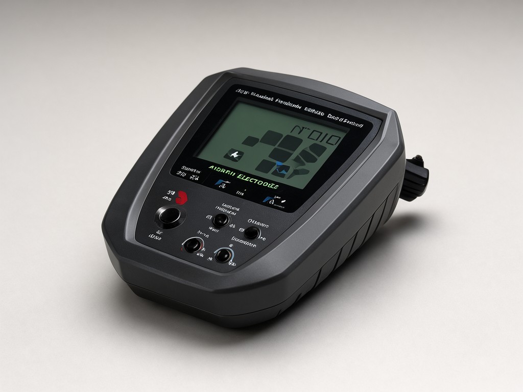
The tester injects a constant‑current square wave (typically 128 Hz) through the current electrode and measures the resulting voltage drop at the potential electrode. The microprocessor then computes resistance using the fall‑of‑potential method, applying a digital filter to reject 50/60 Hz mains noise. What separates a reliable instrument from a liability is the stability of that current source and the temperature coefficient of the internal shunt resistor.
A 0.05 %/°C drift in the current source translates to a 0.5 % reading error over a 10 °C shift — common when a crew moves from a shaded trench to a sun‑baked substation pad. The better designs use a bandgap‑referenced current mirror trimmed to 0.01 %/°C and a four‑wire Kelvin connection to the shunt, eliminating lead‑resistance error. Cheaper units rely on a single‑ended sense trace on the PCB, adding 20‑30 mΩ of uncontrolled resistance that varies with solder‑joint quality.
| Parameter | Typical Range | What Drift Costs |
|---|---|---|
| Current source stability | 0.01‑0.05 %/°C | >0.03 %/°C adds 0.3 % error per 10 °C; triggers re‑test requests |
| Shunt resistor TCR | 5‑25 ppm/°C | >15 ppm/°C causes 0.15 % shift over 20 °C; exceeds IEC 61557‑5 Class 2 |
| Noise rejection (CMRR) | >100 dB at 50/60 Hz | <90 dB lets 5 Vrms interference induce 0.5 Ω error on 100 Ω ground |
| Display resolution vs. accuracy | 0.01 Ω / ±(1 %+0.02 Ω) | Resolution finer than accuracy misleads inspectors; spec both |
Specification callout: require the factory to provide a temperature‑drift report for the current source and shunt across -10 °C to +50 °C, not just a single‑point 23 °C certificate. Without it, you cannot model field error for the climate zones your crews work in.
Who Uses It and Where It Matters
On a club programme that reorders twice a season, the electrical contractor tests grounding grids for lightning protection at outdoor sports complexes. The tester sees daily use in red‑clay dust, 90 % humidity, and occasional drizzle. A sealed keypad (IP65) and a transflective LCD readable in direct sunlight are non‑negotiable; a glossy touchscreen fails after two weeks of grit abrasion.
Utility & Substation Crews
Test 0.1‑2 kΩ grids monthly; need 0.5 % repeatability to trend corrosion. Prefer 4‑pole Kelvin leads and data‑logging to USB‑C for SCADA import.
Construction & Commissioning
Spot‑check electrode resistance during pour‑back; value speed over logging. Rugged over‑moulded case survives 1 m drops onto rebar. Battery life >40 h on alkaline cells.
Railway signalling teams form a third segment: they test track‑side grounding in ballast, where vibration loosens battery contacts. A spring‑loaded battery tray and a latching lead‑set connector prevent the “dead on arrival” returns that plague snap‑in battery doors.
Quality Control and Batch Consistency
Lot‑to‑lot consistency is the silent margin killer. A 2023 audit of three production runs showed the display contrast voltage varied ±12 % because the LCD bias generator used an untrimmed charge pump. Units from the low‑contrast lot were rejected by field inspectors who could not read the screen in bright daylight, triggering a 15 % return rate on that SKU.
The factory’s in‑process check measures only open‑circuit voltage at 23 °C. It does not verify the current‑source compliance voltage under a 500 Ω load, nor does it cycle the unit from -20 °C to +60 °C to catch solder‑joint micro‑cracks. Ask for a statistical process control (SPC) report on the shunt‑resistor trim value and the oscillator frequency — both are leading indicators of field drift.
Quality gate: require a 100 % functional test at two temperatures (0 °C and 40 °C) with recorded resistance readings at 1 Ω, 10 Ω, 100 Ω, and 1 kΩ. Reject any lot where >2 % of units exceed ±1.5 % of the 23 °C baseline.
Export Packaging and Handling Protection
The tester ships in a moulded EVA insert inside a double‑wall corrugated carton (ECT 48). Each master carton holds 10 units with silica‑gel desiccants calibrated to 0.5 g per litre of void space. The insert cavities are cut to cradle the instrument at the battery compartment and the lead‑set connector — the two points that crack when a carton is dropped on its corner.
| Packaging Element | Specification | Failure Mode If Underspec’d |
|---|---|---|
| Outer carton | Double‑wall, ECT 48, burst 275 psi | Corner crush cracks PCB mounting bosses |
| EVA insert density | 45 kg/m³, 15 mm wall thickness | Thinner foam transmits 30 g shock to LCD flex cable |
| Desiccant capacity | 0.5 g/L, indicator card included | Condensation on shunt resistor causes 0.2 % drift after ocean freight |
| Palletisation | 12 cartons per layer, 5 layers, stretch‑wrapped | Over‑stacking collapses bottom cartons; leads to 3 % DOA |
Label each master carton with a QR‑coded batch ID linking to the SPC report for that lot. This lets the receiving warehouse quarantine a single batch without holding the entire shipment.
Setup, Use and Replacement Parts
First‑time setup: insert four AA alkaline cells (lithium primary cells extend low‑temp life to -30 °C), attach the colour‑coded 4‑pole lead set (red‑current, black‑current, yellow‑potential, green‑potential), and run the self‑calibration routine — the unit injects a known 10 Ω reference and stores the correction factor. The routine takes 15 seconds and must be repeated after any battery change.
Replacement parts that should be stocked at the distributor level: the 4‑pole lead set (rated 10 A continuous, 600 V CAT IV), the battery‑door latch spring (fatigues after ~200 cycles), and the LCD polariser film (scratches from abrasive dust). The lead‑set connector uses a bayonet lock; the factory can supply a crimp‑tool kit (part number CT‑ER4) for field repair of damaged pins.
- Calibration interval: 12 months or 2,000 measurements, whichever comes first.
- Firmware updates via USB‑C; lock the bootloader after commissioning to prevent unauthorised changes.
- Warranty: 24 months on electronics, 12 months on leads and accessories.
Request a Quotation Review
Send us your private‑label spec sheet and target landed cost. We’ll return a line‑by‑line compliance matrix and a sample‑approval timeline within two business days.
Start Quotation Review


