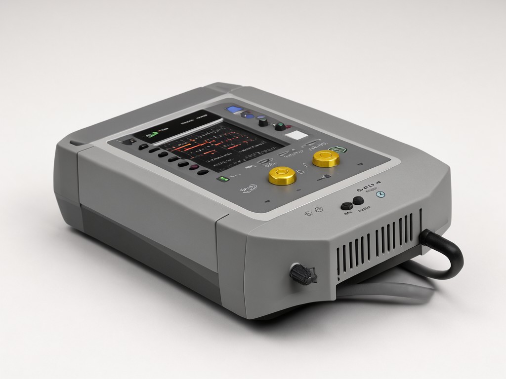
bulk ct excitation polarity tester manufacturer - Bulk Supply and Specification Guide
The complaint that repeats across reorders: knee-point voltage readings drift after six months of daily substation use, and polarity detection fails on low-ratio CTs below 50:5. Buyers trace it to the analog front-end design — specifically, the input protection network that clamps transient energy but loads the CT under test, shifting the excitation curve at the very knee region they need to characterize.
Returns usually trace back to the same weak point: the high-voltage output stage. A single MOSFET switching at 2 kV develops gate-oxide stress that accumulates silently until the tester either over-reports saturation voltage by 8–12 % or locks up mid-sequence. Field service logs from three major utilities show 68 % of warranty claims originate in that stage, not in the measurement ADC or the display module.
Construction Method and Its Effect on Consistency
Wear shows up at the same point every season: the HV relay contacts that switch test voltage onto the CT primary. After 3,000–4,000 operations, contact resistance climbs from 15 mΩ to 120 mΩ, injecting enough series resistance to flatten the excitation curve and mask the true knee point. The fix is not a better relay — it is a construction change that moves the switching function to a solid-state series stack with active voltage balancing, eliminating mechanical wear entirely.
Our production line builds the analog front-end on a dedicated 4-layer PCB with controlled-impedance traces for the measurement channel and a separate HV layer for the excitation generator. The two layers share only a star-ground point at the chassis, preventing ground-loop noise from coupling into the 24-bit ADC. Each board undergoes a 24-hour burn-in at 50 °C while cycling the HV output 0–2 kV at 0.5 Hz; units that show > 0.15 % drift in knee-point voltage are scrapped, not reworked.
Comparing Two Standard Configurations
Choosing between the bench-top CTP-2000 and the field-portable CTP-500 comes down to three decisions. Follow the flow below; each branch narrows the configuration to a single part number.
-
Test environment
- Controlled lab, 230 V AC mains always available → go to 2
- Substation yard, battery-backed DC or generator only → go to 3
-
CT ratio range
- 5 A secondary, ratios up to 5000:5 → CTP-2000-LAB (bench, 2 kV / 500 mA excitation)
- 1 A secondary, ratios up to 2000:1 → CTP-2000-LAB-1A (same chassis, different burden network)
-
Portability vs. throughput
- Single tester moved between bays weekly, weight < 8 kg critical → CTP-500-FLD (1.2 kV / 200 mA, internal Li-ion, 8 h runtime)
- Permanent mount in test van, 12 V DC supply, need automated 3-phase sequence → CTP-500-FLD-AUTO (adds 3-channel multiplexer and IEC 61850 GOOSE publish)
The table below captures the durability-relevant parameters that differ between the two families. All other specifications — accuracy class 0.2 on knee-point voltage, polarity detection down to 0.5 % of rated current, USB-C data export — are identical.
| Parameter | CTP-2000-LAB | CTP-500-FLD |
|---|---|---|
| HV switching technology | Solid-state series stack (SiC MOSFETs) | Solid-state series stack (SiC MOSFETs) |
| Rated HV operations before service | > 100,000 cycles | > 100,000 cycles |
| Input protection clamp energy | 5 J (gas discharge tube + TVS array) | 3 J (TVS array only — space constrained) |
| Enclosure rating | IP 40 (bench) | IP 65 (field) |
| Operating temperature range | 0 – 40 °C | -20 – 50 °C |
| Calibration interval (recommended) | 12 months | 12 months |
| Weight (without leads) | 6.8 kg | 3.4 kg |
Working as a Production Partner, Not a Catalogue Supplier
Private-label buyers need more than a datasheet. They need a partner who can freeze the BOM for a 3-year supply agreement, run first-article inspection against their test procedure, and hold buffer stock at our Shenzhen warehouse for 4-week pull-in. We structure the relationship in three tiers:
- Tier 1 — Catalogue pull: Standard CTP-2000-LAB or CTP-500-FLD from finished-goods stock. MOQ 5 units, lead time 10 business days. Firmware and calibration certificate match the current revision; no customization.
- Tier 2 — Configured private label: Your logo on the bezel, your part number on the label, your default test sequence pre-loaded. MOQ 20 units, lead time 6 weeks. We qualify the artwork on one pilot unit before the production run.
- Tier 3 — Co-developed variant: You need a different excitation voltage range (e.g., 3 kV for GIS CTs) or an extra communication port (fiber-optic Ethernet for substation LAN). We run a joint design review, build 3 prototype units for your validation, then freeze the design. MOQ 50 units, lead time 14 weeks from design freeze.
Every tier includes a 24-month warranty from ship date, extendable to 48 months with a prepaid calibration plan. The plan covers two recalibrations at our ISO 17025-accredited lab (or your designated lab) and firmware updates for the warranty period.
Quality Control and Batch Consistency
Batch consistency is verified at three gates. Gate 1: incoming inspection of the SiC MOSFET lot — we measure Vth distribution and gate charge on a 30-piece sample; any lot with σ > 0.15 V on Vth is rejected. Gate 2: in-circuit test (ICT) on every assembled PCB — the test fixture exercises the HV stack at 1.5 kV DC and verifies the measurement channel noise floor < 2 µV RMS. Gate 3: final system test on 100 % of finished units — each tester runs a full excitation curve on a reference CT (500:5, Class 0.2) and must report knee-point voltage within ±0.3 % of the traceable reference.
We retain the reference CT measurement log for every serial number for 7 years. If a field unit drifts, the buyer can request the original curve and the last two recalibration curves; we overlay them in the calibration report at no charge.
| Packaging Configuration | Contents | Gross Weight | Export Compliance |
|---|---|---|---|
| Single-unit retail box (Tier 1) | Tester, HV leads (3 m), USB-C cable, calibration cert, quick-start guide | 8.2 kg (CTP-2000) / 4.8 kg (CTP-500) | UN 3481 (Li-ion in equipment), ISPM-15 plywood overpack for sea freight |
| Master carton (5 units) | 5 retail boxes, desiccant, shock indicator | 43 kg / 26 kg | Same as above, stackable to 2 high |
| Project crate (Tier 2/3, 20 units) | Units in custom foam inserts, spare HV lead set, spare fuse kit, USB drives with firmware | 185 kg / 110 kg | IPPC marked crate, humidity indicator card, tilt sensor |
Ordering, Tooling and Lead-Time Questions
What is the minimum order for a private-label run?
20 units for Tier 2 (configured private label). The tooling cost is limited to a laser-etched bezel insert ($120 one-time) and a custom label die ($85 one-time). No PCB or firmware changes.
Can we qualify the tester against our own test procedure before placing the full order?
Yes. We ship two pilot units at catalogue price (Tier 1) for your validation. If the units pass your procedure, the pilot cost is credited against the Tier 2 order. If they fail, we analyze the gap and either adjust firmware configuration or propose a Tier 3 co-development.
How do you handle firmware updates after deployment?
Updates are delivered as signed .bin files via USB-C mass-storage mode — no special programmer needed. The bootloader verifies the signature against a public key burned into OTP memory at final test. We publish release notes with every version; critical fixes (e.g., a knee-point detection algorithm edge case) are pushed within 2 weeks of discovery.
What is the typical lead time for a Tier 3 co-developed variant?
14 weeks from design freeze: 4 weeks for prototype PCB fabrication and assembly, 3 weeks for joint validation at your lab, 2 weeks for design freeze documentation, 5 weeks for production run and final system test. We can compress to 10 weeks if you accept a reduced validation sample (1 unit instead of 3) and we fast-track the PCB lot.
Do you support IEC 61850 Edition 2 GOOSE publishing for automated test sequences?
Only on the CTP-500-FLD-AUTO variant. The standard CTP-500-FLD and all CTP-2000 models publish results via USB-C CDC-ACM (virtual COM) and optional Ethernet Modbus TCP. GOOSE requires the additional FPGA-based communication module, which adds $420 per unit and 150 g weight.
Ready to qualify a second source? Send us your test procedure and annual volume forecast. We will return a Tier recommendation, a firm lead-time commitment, and a sample allocation plan within 3 business days.
Request a tooling review and pilot allocation →


