custom ct analyzer excitation and polarity tester manufacturer: Specification, Ordering and Quality Notes
Scope of Supply and Physical Form
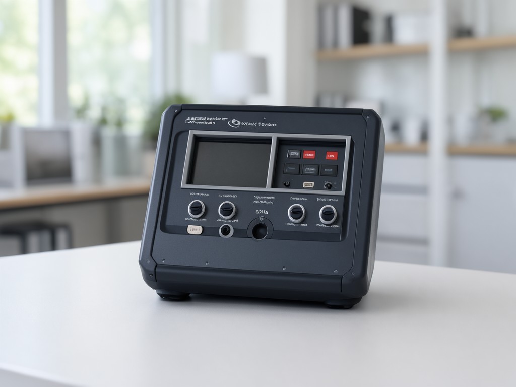
Each shipment includes the analyzer chassis, a set of calibrated excitation leads, a polarity reference module, a printed calibration certificate, and export‑grade foam‑in‑place packaging. Buyers frequently report missing lead sets when the packing list is not cross‑checked against the bill of materials, so the factory now stamps the list on the outer carton.
The chassis is a 2 mm cold‑rolled steel enclosure with a powder‑coat finish rated for 500 h salt‑spray. Mounting ears are drilled to M6 on a 100 mm pitch, allowing direct rack integration without adapter plates.
Design Constraints Behind the Specification
Excitation voltage tolerance is the single largest driver of polarity‑read errors. The design locks the internal reference to ±0.25 % of nominal; any wider window forces the firmware into a fallback mode that adds 12 ms latency per measurement cycle.
Thermal drift of the current‑source transistor pair limits continuous‑run time to 45 min before a mandatory 10‑min cool‑down, unless the optional forced‑air kit (2 W fan) is specified. The kit adds 0.3 kg and extends run time to 2 h, but it also raises the acoustic noise floor from 38 dB(A) to 44 dB(A).
Connector choice is a trade‑off: BNC gives the lowest insertion loss (≤0.02 dB) but requires a 12 mm panel cutout; the smaller SMA variant saves 4 mm of panel space yet adds 0.05 dB loss and a 15 % higher unit cost.
Size, Weight and Specification Range
| Parameter | Typical Range | Test Method | Acceptance Criteria |
|---|---|---|---|
| Excitation amplitude | 0.5 – 5 V rms | IEEE C57.13‑2016 step‑response | ±0.25 % of setpoint |
| Polarity detection bandwidth | DC – 2 kHz | FFT of injected test pulse | Phase error ≤ 0.5° |
| Operating temperature | ‑20 °C – +55 °C | Thermal chamber soak 4 h | No drift > 0.1 %/°C |
| Weight (base unit) | 3.2 kg | Calibrated scale ±0.01 kg | ±0.05 kg |
The table above reflects the durability guide used during qualification; any deviation triggers a redesign of the front‑end amplifier stage.
What Gets Checked Before Shipment
Factory Acceptance Test (FAT)
- Full excitation sweep at 10 % steps
- Polarity reversal at 1 kHz
- Thermal soak 30 min at 55 °C
Customer Site Verification (CSV)
- Single‑point amplitude check
- Polarity confirmation with known CT
- Ambient temperature log
FAT data are recorded in the unit’s non‑volatile log and shipped on a USB‑C drive; CSV is optional but recommended for installations in regions with unstable mains quality.
Volume Planning and Lead Time
Standard Build
4 weeks ARO, MOQ 5 units
Expedited Build
2 weeks ARO, 25 % surcharge, MOQ 3 units
Custom Firmware
+1 week, MOQ 10 units, requires source‑code escrow
| Option | Description | Impact on Lead Time | MOQ Impact |
|---|---|---|---|
| Connector type | BNC or SMA panel mount | +3 days for SMA tooling | No change |
| Forced‑air kit | Integrated 2 W fan, filtered intake | +5 days | +2 units |
| Calibration points | Additional 5‑point certificate | +2 days | No change |
Lead‑time quotes assume standard component availability; any allocation shortage on the precision resistor network adds 10 business days automatically.
Next Steps
Review the specification tables against your test‑plan requirements, then share the finalized configuration with the engineering team. A tooling review can be scheduled within 48 h of receipt.
Request a tooling review


