oem potential transformer testing equipment factory: What Buyers Should Check Before Ordering
What This Product Is and Where It Fits
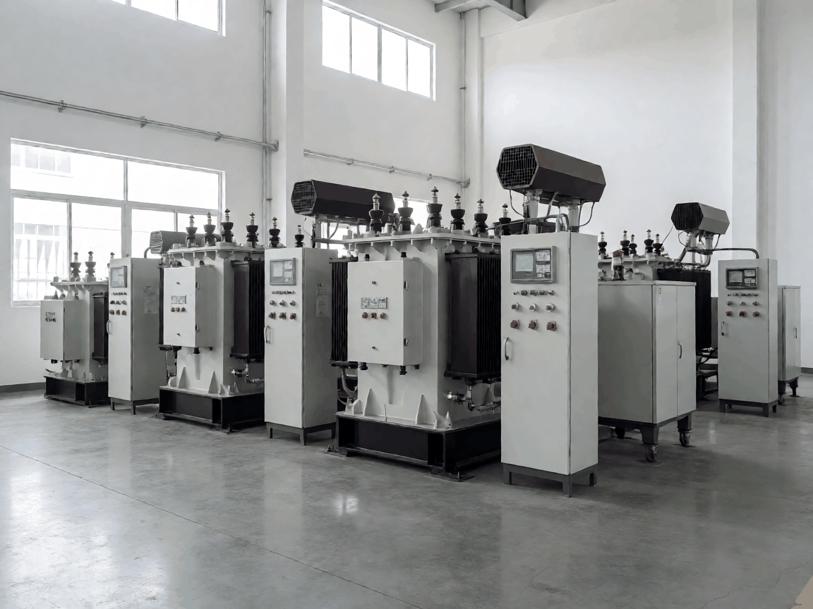
Potential transformer (PT) testing equipment validates ratio accuracy, polarity, burden capacity, and insulation integrity of instrument transformers before they enter service in substations, switchgear assemblies, and protection relay panels. The test sets range from portable single-phase ratio meters rated to 0.1% accuracy through three-phase automated benches that sweep burden from 2.5 VA to 200 VA while logging temperature rise. Buyers specify these systems for incoming QC at transformer OEMs, utility maintenance depots, and third-party calibration labs that issue traceable certificates.
A typical configuration pairs a precision voltage divider (0.05% class) with a burden box offering discrete steps — 2.5, 5, 10, 15, 25, 30, 50, 75, 100, 150, 200 VA — and a polarity indicator that resolves 30° phase displacement. The divider and burden box share a common ground reference to eliminate common-mode error when testing 11 kV/110 V or 33 kV/110 V PTs. Most factories ship the divider, burden box, and controller as separate modules that lock into a 19-inch rack frame; the frame depth determines whether the set fits standard 600 mm or 800 mm cabinets.
How It Performs in Use
Ratio error stays within ±0.05% from 80% to 120% rated primary voltage when the divider uses 0.01% wire-wound resistors temperature-compensated to 5 ppm/°C. Cheaper film-resistor dividers drift 0.02% over a 10 °C shift — enough to push a 0.2 class PT out of tolerance at the 120% overvoltage point. Polarity indication updates in 200 ms, letting an operator confirm 300 transformers per shift without waiting for a null detector to settle.
Burden switching uses sealed relays rated for 10⁶ operations at 250 V AC. A factory that specs 10⁴-cycle relays sees contact resistance climb past 50 mΩ after 18 months, adding 0.03% ratio error at 200 VA. The controller firmware should log each test with timestamp, PT serial number, ambient temperature, and all burden steps — labs that skip the temperature field cannot defend certificates when a utility audits a batch six months later.
How It Is Built and What That Changes
The divider housing is machined from 6061-T6 aluminum, 12 mm wall thickness, to shield the resistor string from EMI generated by nearby breaker operations. Plastic enclosures save 1.8 kg per module but fail the 10 V/m radiated immunity test (IEC 61000-4-3) required for substation environments. Burden resistors are wire-wound on ceramic cores, potted in epoxy with 1.5 kV isolation to ground; the potting compound must pass 1000 h at 85 °C / 85% RH without cracking or the resistance shifts 0.1% under humid coastal conditions.
Controller boards use conformal-coated FR-4 with 2 oz copper pours for the relay drive lines. A factory that skips conformal coating sees corrosion on the relay drivers within 14 months in Gulf Coast humidity, causing stuck relays that report wrong burden values. The front-panel display should be a 7-inch capacitive touch LCD rated −20 °C to 60 °C; resistive screens delaminate after 500 thermal cycles between cold storage and substation heat.
Wire-Wound Divider (0.05% Class)
- Tempco ≤ 5 ppm/°C
- Stability 0.01% / year
- Weight: 4.2 kg
- Cost premium: +35% vs film
Film-Resistor Divider (0.1% Class)
- Tempco 25–50 ppm/°C
- Stability 0.05% / year
- Weight: 2.4 kg
- Lower upfront cost
Buying Mistakes That Lead to Returns
Ordering a single-phase set when the utility tests three-phase PT banks forces technicians to rotate leads manually, adding 12 minutes per transformer and introducing polarity errors. A three-phase automated bench with motorized phase switching pays back in labor savings at 50 units per month. Specifying 0.2% accuracy because the data sheet says "meets IEC 61869" without confirming the divider class — the standard permits 0.2%, 0.5%, and 1.0% classes — leaves the buyer with a set that cannot certify 0.2 class PTs.
Skipping the temperature-compensation option on the divider saves $420 per unit but generates 0.02%/°C drift. In a Middle Eastern depot where ambient swings 25 °C between winter night and summer noon, that drift exceeds the 0.1% error budget for 0.2 class PTs. Another common omission: no provision for external reference standard input. Labs that later need to cross-check against a national lab reference must retrofit a BNC input and recalibrate the firmware — a $1,800 field kit plus two days downtime.
Volume Planning and Lead Time
Tooling for the aluminum divider housing amortizes at 30 units; below that quantity the factory adds a $2,200 setup charge per variant. Burden relay boards share a common PCB across all VA ratings — only the resistor values change — so a mixed order of 10× 50 VA and 10× 200 VA sets incurs no extra tooling. Controller firmware is flashed in-circuit; custom branding (boot logo, menu colors, report header) adds three days to lead time but no unit cost if the artwork is supplied as vector SVG with Pantone references.
Standard lead time: 6 weeks for 1–5 units, 8 weeks for 6–20, 10 weeks for 21–50. The bottleneck is divider resistor matching — each string requires 12 resistors hand-selected to 0.005% tolerance and aged 72 hours at 60 °C before potting. A factory that claims 4-week lead time for 20 units is either skipping the aging step or holding pre-matched resistor kits (rare above 10 sets). Ask for the aging log; a legitimate factory provides it with the test certificate.
| Order Quantity | Lead Time | Tooling Charge | Unit Cost Index (1 pc = 1.00) |
|---|---|---|---|
| 1–5 | 6 weeks | $2,200 per variant | 1.00 |
| 6–20 | 8 weeks | Waived at 10+ | 0.88 |
| 21–50 | 10 weeks | Waived | 0.79 |
| 50+ | 12 weeks | Waived | 0.72 |
Stock Availability and Reorder Planning
The factory keeps finished divider modules (0.05% class, 11 kV/110 V ratio) in stock at 8–12 units. Burden boxes are built to order because the VA step configuration varies by market — European utilities prefer 10/25/50/100 VA steps, North American specs call for 15/30/75/150 VA. Controllers are generic; the firmware loads the correct step table at first boot. A buyer who commits to a 12-month blanket order with monthly releases can lock the divider stock and pull burden boxes on 3-week lead time.
Reorders after 18 months often hit a component obsolescence wall: the 24-bit ADC used in the controller goes end-of-life, forcing a board respin. The factory should quote a 5-year component availability guarantee or provide a firmware-compatible replacement board design. Without it, a repeat order in year three becomes a new product qualification — full type test, new certificate, new training. One utility buyer absorbed $47,000 in revalidation costs because the factory changed the ADC without notice.
Export Packaging and Handling Protection
Each module ships in a custom-cut polyethylene foam insert inside a double-wall corrugated carton (ECT 48) rated for 1.5 m drop on concrete. The divider module includes a tilt indicator and a shock recorder set to 15 g threshold — if the recorder trips, the factory requires photos before honoring warranty. Rack frames ship bolted to a plywood pallet with four M12 lifting eyes; ocean freight in 20-foot containers typically stacks two frames high with 150 mm dunnage between layers.
Humidity control: the divider and burden boxes each include a 50 g desiccant sachet and a humidity indicator card (10/20/30% RH). Cards showing 30% pink at receipt mean the carton seal failed — the factory will request the card photo and replace the desiccant at no charge, but the buyer must re-verify divider tempco before first use. Labeling follows IPPC ISPM-15 for wood packaging; the factory stamps the pallet, not the cartons. Missing stamps cause customs holds at EU and Australian ports, adding 7–10 days and $350–600 in demurrage.
| Test Parameter | Acceptance Criterion | Test Method | Frequency |
|---|---|---|---|
| Ratio Accuracy (0.05% class) | ±0.05% at 80–120% Vn | Comparison vs 0.01% reference divider | 100% production |
| Polarity Resolution | ≤ 0.5° phase error | Three-phase reference PT at 30° lag | 100% production |
| Burden Step Accuracy | ±1% of nominal VA | Precision power analyzer at 0.2 PF | 100% production |
| Insulation Resistance | ≥ 10 GΩ at 500 V DC | Megohmmeter, 60 s dwell | 100% production |
| Dielectric Withstand | 2 kV AC, 1 min, no flashover | Hipot tester, 5 mA trip | 100% production |
| EMC Radiated Immunity | 10 V/m, 80–1000 MHz, criterion A | Anechoic chamber per IEC 61000-4-3 | Type test + 10% batch |
| Temperature Cycling | −20 °C to +60 °C, 10 cycles, ratio shift ≤ 0.01% | Climate chamber, powered monitoring | Type test |
| Relay Endurance | Contact resistance ≤ 20 mΩ after 5×10⁵ cycles | Automated switching at rated VA | Type test |
Next Steps: Artwork and Branding Review
Send your logo vector file (SVG or AI), Pantone color codes, and preferred report header layout to the engineering contact. The factory will return a firmware mockup screenshot and a laser-etch proof for the front panel within 48 hours. Approval locks the branding into the production traveler — no changes after the first controller board is flashed. For volume schedules, divider aging logs, or a sample test certificate from the last batch, use the link below.


