factory direct advanced contact resistance measurement tester factory: Specification, Ordering and Quality Notes
What the Design Has to Balance
Wear shows up at the same point every season: the four-wire Kelvin probes that see thousands of insertion cycles on production lines. A tester that drifts 0.5 mΩ after 10k cycles forces a recalibration stoppage that costs more than the unit price difference between a hardened probe tip and a standard one.
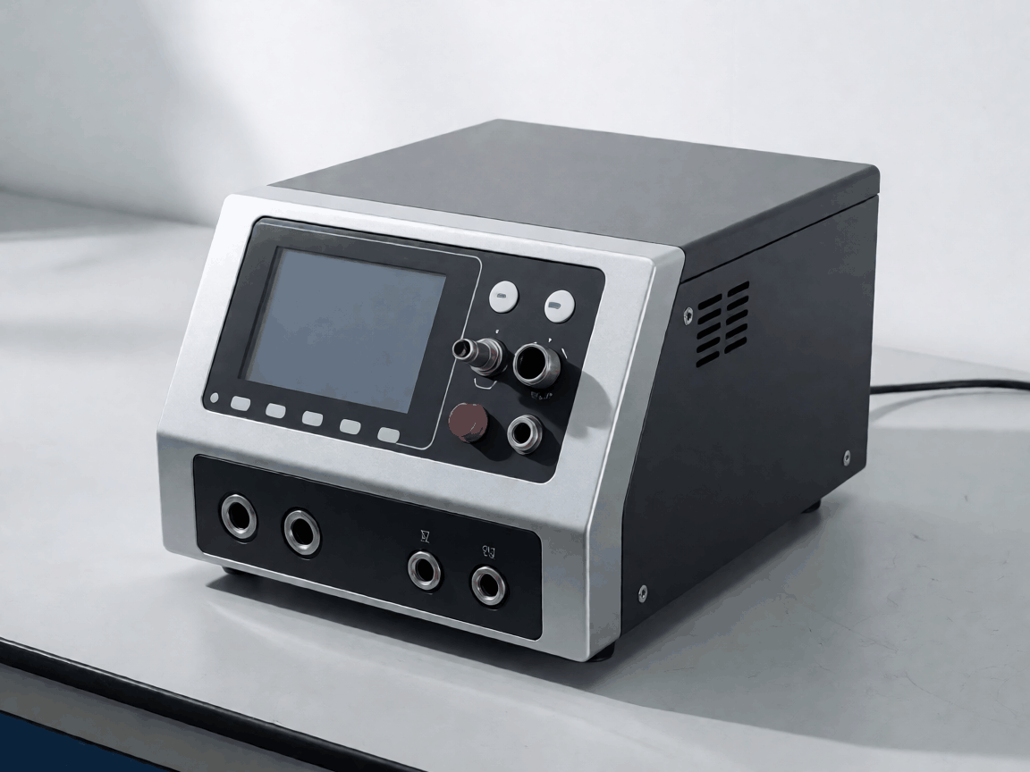
The enclosure has to survive bench drops and solvent wipes without cracking the display bezel. We specify 3 mm aluminum front panels with a chemical-resistant powder coat, not because it looks premium but because a cracked bezel lets moisture into the front-end amplifier and shifts the zero offset by microvolts.
Thermal management is the hidden trade-off. A fanless design keeps acoustic noise down for lab use, but the 10 A test current option dissipates 4 W in the shunt network. We solve it with a die-cast chassis that doubles as a heatsink, adding 300 g but eliminating the failure mode of a seized fan in dusty environments.
Measurement Range
0.1 µΩ – 2 Ω, four ranges auto or manual
Test Current
10 mA, 100 mA, 1 A, 10 A selectable
Resolution
0.01 µΩ on 2 mΩ range
Accuracy
±(0.05 % rdg + 0.005 % rng) at 23 °C ±5 °C
Segment-Specific Requirements
Most quality disputes start with a consistency gap between the lab qualification unit and the production batch. A distributor buying 50 units for resale needs each tester to ship with a traceable calibration certificate and identical firmware revision. An OEM integrating the module into an automated harness tester needs the same command set over USB and RS-232, plus a 50-pin D-sub for handler interface.
| Application Segment | Typical Test Current | Interface Must-Haves | Environmental Rating | Calibration Cycle |
|---|---|---|---|---|
| R&D / Metrology Lab | 10 mA – 1 A | USB, GPIB, LAN, trigger I/O | IP20, 15–35 °C | 12 months, ISO 17025 |
| Production Line (Wire Harness) | 1 A – 10 A | RS-232, handler 50-pin, PLC pass/fail | IP40, 0–45 °C, vibration 2 g | 6 months, in-house standard |
| Field Service / Utility | 100 mA – 1 A | Bluetooth, USB-C, battery 8 h | IP54, -10–50 °C, drop 1 m | 12 months, field verification |
| EV Battery Module Assembly | 10 A continuous | EtherNet/IP, safety interlock, dual probe | IP54, 0–40 °C, EMI hardened | 3 months, statistical process control |
OEM and ODM Programme Structure
Returns usually trace back to the same weak point: firmware that wasn't regression-tested against the buyer's handler protocol. Our OEM programme locks the firmware branch at golden-sample approval and tags every production build with a SHA hash on the calibration label.
Private-label buyers get a choice of three front-panel branding levels: silk-screen logo only, custom membrane keypad with colour-matched overlays, or full bezel redesign with integrated mounting ears. The keypad tooling adds 4 weeks and $2,800 but eliminates the membrane-delamination returns that plague low-cycle membrane switches.
MOQ and Lead-Time Trade-Offs
Standard configuration: 10 units, 3 weeks ARO. Custom keypad: 50 units, 7 weeks. Full bezel redesign: 100 units, 10 weeks including EMC pre-scan. Blanket orders with quarterly releases lock unit price and guarantee allocation of the 10 A shunt alloy lot.
Quality Control and Batch Consistency
Every unit passes a 4-hour burn-in at 40 °C while cycling through all four test currents. We log the zero-drift and gain-drift per channel; any unit exceeding 0.02 %/°C on the 2 mΩ range is pulled for shunt re-selection.
Probe tips are the highest-wear component. We run a 50k insertion cycle test on 5 % of each batch using a motorised fixture that mates a gold-plated test coupon. Tip resistance must stay below 5 mΩ end-of-life. The test data travels with the batch as a QR-coded PDF on the shipping carton.
Statistical process control charts for the front-end amplifier offset voltage are reviewed weekly. A shift of 0.3 µV triggers a lot hold and root-cause analysis before the next build. This is the metric that correlates with field calibration failures 18 months later.
Care, Storage and Service Life
Store probes in the supplied anti-static tubes with the protective caps on. A single unprotected tip contact with a stainless bench edge adds 2–3 mΩ permanent contact resistance.
Battery-backed real-time clock holds calibration date for 10 years. Replace the CR2032 when the low-bat icon appears; loss of date stamp invalidates the calibration certificate for regulated environments.
- Clean probe tips with 99 % isopropyl and lint-free swabs; abrasive pads remove the gold plating.
- Verify zero offset weekly with the supplied shorting bar; log the reading for trend analysis.
- Firmware updates via USB mass storage; never interrupt power during the 90-second flash cycle.
- Recalibration recommended at 12 months or 20k measurements, whichever comes first.
Expected service life: 7 years in lab use, 4 years on a two-shift production line with 10 A continuous duty. The limiting factor is the relay contact erosion on the range-switching matrix; we stock replacement relay boards for 10 years after last shipment.
Project Discussion
Ready to define the exact configuration for your application? Share your test current, interface, and volume targets and we'll return a firm quote with a lead-time commitment and a sample calibration report.


