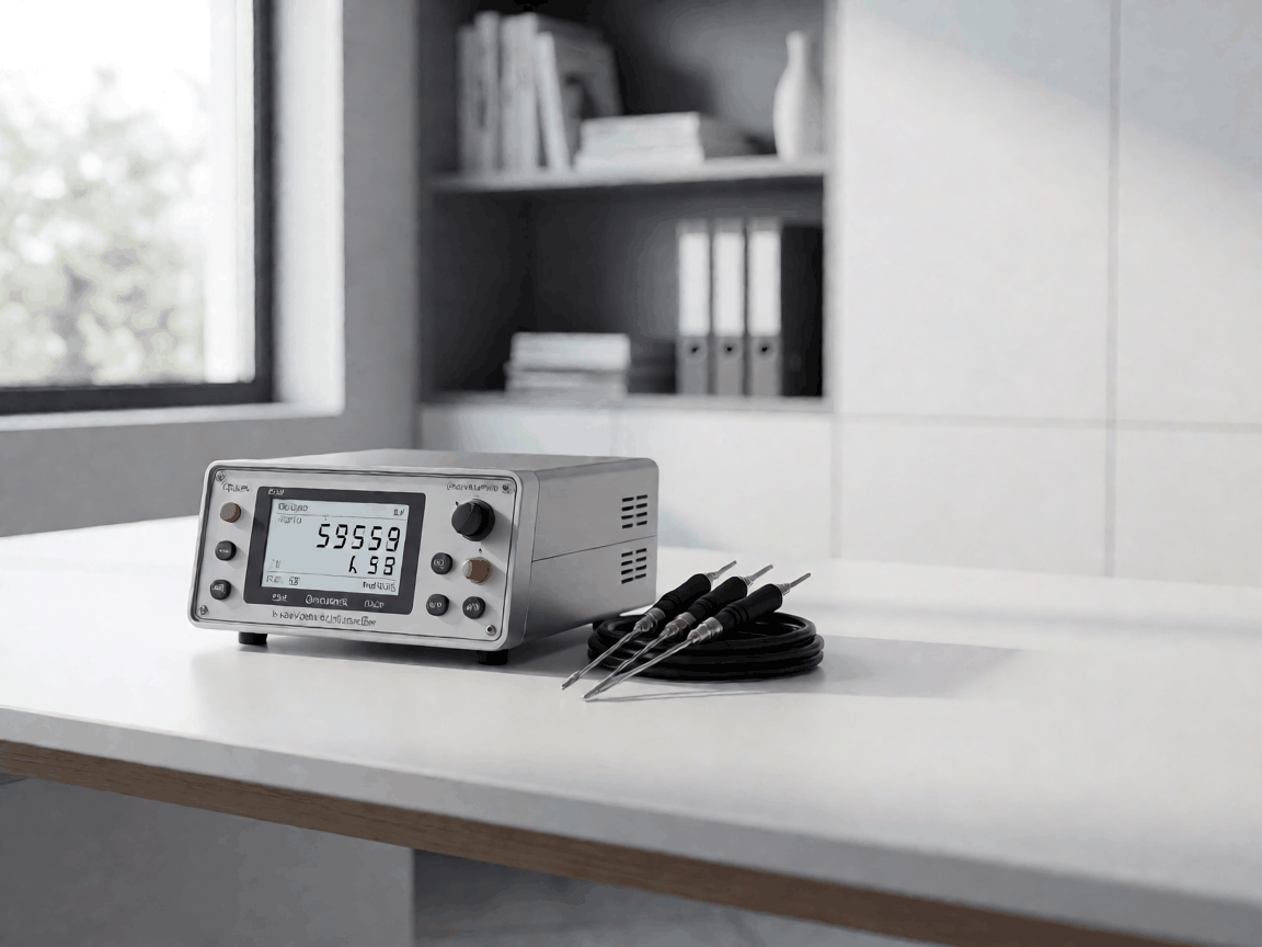
Specifying wholesale high precision micro-ohmmeter suppliers for Wholesale and OEM Orders
The Problem Buyers Keep Paying For
The interface between parts determines whether a micro-ohmmeter survives a production line or drifts into scrap within six months. Buyers who chase the lowest unit price on a datasheet often discover that the real cost lives in recalibration cycles, failed first-article inspections, and the freight bill for returning instruments that cannot hold spec across a 10 °C shift.
A typical complaint arrives as a batch of 50 units where three read 15 ppm high at 1 mΩ, two develop intermittent Kelvin-lead contact after 200 insertion cycles, and the lot traceability paperwork references a firmware revision the factory never shipped. That variability forces the receiving QC team to burn an extra shift verifying each unit against a lab standard — time the launch schedule does not have.
What Actually Determines Performance
Consistency depends on the thermal-EMF budget of the analog front-end more than the ADC resolution advertised on the front panel. A 24-bit converter backed by a 50 nV/°C input stage will outperform a 28-bit part fed by 200 nV/°C drift every time the ambient temperature walks away from 23 °C.
The current source architecture decides the usable measurement window. Pulsed 1 A / 10 A dual-range sources with active compliance limiting protect delicate shunt resistors and battery tabs from self-heating error, while continuous 100 mA sources suit bus-bar and connector qualification where thermal mass absorbs the dissipation. Matching the source profile to the device-under-test prevents the "works on the bench, fails on the line" gap.
Four-wire Kelvin switching relays must be hermetically sealed, low-thermal-EMF reed or solid-state types. Open-frame signal relays introduce microvolt-level offsets that swamp the 1 µΩ resolution buyers expect at the 1 mΩ range. The relay drive circuitry also needs controlled dV/dt to avoid injecting charge into the measurement loop during range changes.
Construction Method and Its Effect on Consistency
The enclosure is not cosmetic. A die-cast aluminum chassis with internal ribbing serves as both EMI shield and thermal ballast. When the 10 A pulse fires, the chassis absorbs the transient heat so the reference amplifier junction temperature moves less than 0.5 °C. Plastic housings, even with metallized coating, cannot match this thermal inertia and show measurable zero-shift during rapid-fire testing.
Connector choice locks in serviceability. LEMO 00-series push-pull for the Kelvin leads withstand 5,000 mating cycles with <0.5 mΩ contact resistance repeatability. Banana jacks save $3 per unit but add 2–3 mΩ variance per insertion — unacceptable for 0.01 % accuracy class. The rear-panel USB/LAN/IEEE-488 block should be a single modular insert so a damaged port swaps in five minutes without breaking the calibration seal.
Where This Product Beats Standard Alternatives
Balance and load analysis shows the pulsed 10 A source with 20 ms on-time delivers 0.02 % reading accuracy on 100 µΩ shunts without measurable self-heating, while bench-grade 1 A continuous sources require 30-second soak and still leave 0.1 % uncertainty from thermal drift.
The guarded front-end holds calibration through -10 °C to 50 °C ambient swings without software correction tables. Competitors relying on polynomial compensation in firmware show residual errors of 15–30 ppm/°C at the range extremes — enough to fail automotive battery-tab specs that demand 50 ppm total error budget.
Field-replaceable Kelvin lead sets with color-coded kelvin clips cut downtime. A production cell can swap a worn lead set in 90 seconds and verify with the built-in lead-resistance check, versus shipping the whole instrument back for a $400 recalibration and two-week turnaround.
How to Choose Before Requesting a Quote
| Decision Point | Option A | Option B | Trade-off |
|---|---|---|---|
| Lowest resistance range | 10 µΩ (100 µΩ range, 10 A) | 100 µΩ (1 mΩ range, 1 A) | Option A needs forced-air cooling in fixture; Option B fits handheld form factor |
| Temperature coefficient | < 2 ppm/°C (guarded analog) | 5–10 ppm/°C (firmware compensated) | Option A adds $120 BOM; Option B risks spec escape at temperature extremes |
| Kelvin lead interface | LEMO 00, field-replaceable | Fixed 4-wire cable, factory service only | Option A enables 24/7 line uptime; Option B lowers unit cost by $45 |
| Calibration interval | 12 months (traceable to NMI) | 6 months (internal reference only) | Option A matches ISO 9001 audit expectations; Option B halves recal budget but doubles audit risk |
Segment-Specific Requirements
Automotive Battery Module Line
Needs 10 A pulsed source, 10 µΩ resolution, and IP54 front bezel for coolant mist. The firmware must support pass/fail GPIO output timed to the press-cycle PLC. Barcode scanner integration for DUT serialization is mandatory — manual entry adds 8 seconds per cell and breaks takt time.
Aerospace Harness Qualification
Requires 1 mΩ range at 100 mA continuous to avoid heating lightweight alloy splices. IEEE-488.2 command set with SCPI 1999 compliance for legacy ATE racks. Calibration certificate must reference MIL-STD-45662A traceability chain; commercial ISO 17025 alone gets rejected by the quality engineer.
Solar Junction Box Final Test
High channel count (12–24 DUTs per instrument) via external scanner matrix. Single instrument drives the matrix; per-channel timestamped logs feed the MES. Dust-proof sealed front panel (IP6X) survives the tabbing-stringer debris. 24 V DC power input allows rack mounting on the line without AC drops.
Quality Control and Batch Consistency
Every unit ships with a 17-point calibration report at 23 °C ±1 °C, 40 % RH ±10 %, traceable to the national metrology institute through a primary 1 mΩ standard resistor. The report includes as-found / as-left data at 10 µΩ, 100 µΩ, 1 mΩ, 10 mΩ, 100 mΩ, and 1 Ω ranges, both polarities, with uncertainty budgets expanded to k=2.
Lot acceptance testing runs a 48-hour thermal cycle (-10 °C to 50 °C, 1 °C/min ramp) on a statistical sample (n=5 per 100 units). Units exceeding 15 ppm total drift across the cycle trigger a full-lot hold and root-cause investigation. The test jig logs chamber temperature, instrument reading, and reference standard simultaneously — no manual transcription.
Vibration profile per IEC 60068-2-64 (random, 5–500 Hz, 1.9 g RMS, 30 min/axis) verifies relay contact stability and BGA solder integrity on the DSP board. Post-vibration calibration shift must stay within 5 ppm. Units that pass receive a tamper-evident calibration seal with QR code linking to the digital certificate on the supplier portal.
Next Steps
Send the target resistance range, test current profile, environmental envelope, and integration protocol (SCPI, Modbus, GPIO, or proprietary API). We return a marked-up specification sheet highlighting which line items are fixed by physics and which have cost-flexible alternatives, plus a lot-size vs. lead-time curve for the next three production windows.
Request a specification review


